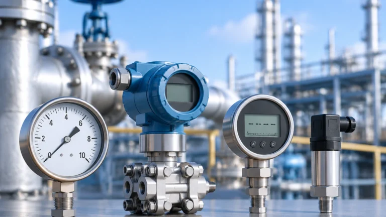
Inline Pressure Transmitter
Inline Pressure Transmitter
In the landscape of industrial automation and process control, the inline pressure transmitter serves as a fundamental component for monitoring system health, ensuring safety, and managing inventory. Unlike submersible sensors or remote-seal systems, an inline pressure transmitter is designed for direct mounting into piping or vessel walls. This configuration provides a robust, compact, and highly responsive solution for measuring the pressure of liquids, gases, and steam. For engineers and facility managers, understanding the nuances of these devices is essential for optimizing process efficiency and maintaining the integrity of industrial systems.
Understanding Inline Pressure Transmitter Technology
An inline pressure transmitter is a field-mounted instrument that converts mechanical pressure into an electrical signal, typically 4-20 mA, 0-10V, or a digital protocol like HART or Modbus. The term "inline" refers to its installation method: the device is threaded or flanged directly into the process line. This direct contact with the medium allows for real-time data acquisition with minimal lag, which is critical in dynamic systems such as high-pressure steam lines or rapid-flow water treatment facilities.
These instruments are versatile. While their primary function is to measure gauge, absolute, or differential pressure within a pipe, they are also frequently employed in hydrostatic level measurement. By installing an inline pressure transmitter at the base of a tank, the weight of the liquid column above the sensor can be translated into a precise level reading. This dual-purpose nature makes them a staple in the product catalogs of professional manufacturers like Welk, where they complement other technologies such as radar and ultrasonic sensors found on the Main Page.
Measurement Principles and Sensor Types
Before selecting an inline pressure transmitter, it is vital to understand the underlying measurement principles. Most modern transmitters utilize one of two primary sensing technologies: piezoresistive or ceramic capacitive.
Piezoresistive Sensors
These sensors consist of a silicon-based diaphragm with embedded strain gauges. When process pressure is applied, the diaphragm deflects, causing a change in the electrical resistance of the strain gauges. This change is measured using a Wheatstone bridge circuit and converted into a standardized output. Piezoresistive sensors are highly sensitive and capable of measuring very low pressures, but they often require an internal fill fluid (such as silicone oil) to protect the silicon element from the process medium.
Ceramic Capacitive Sensors
In this design, a ceramic diaphragm acts as one plate of a capacitor. As pressure moves the diaphragm closer to a fixed ceramic substrate, the capacitance changes. This technology is inherently robust because ceramic is extremely hard and resistant to abrasion and chemical attack. Furthermore, ceramic capacitive sensors are "dry" sensors, meaning they do not require fill fluids, eliminating the risk of process contamination in the event of a diaphragm rupture.
Hydrostatic Level Measurement with Inline Transmitters
One of the most common B2B applications for an inline pressure transmitter is hydrostatic level measurement. The principle is based on the relationship between pressure, liquid density, and height:
P = ρ × g × h
Where:
* P is the pressure (Pa or bar)
* ρ (rho) is the density of the liquid (kg/m³)
* g is the acceleration due to gravity (9.81 m/s²)
* h is the height of the liquid column (m)
In a vented (open) tank, a single inline pressure transmitter at the bottom measures the hydrostatic pressure. If the density of the liquid is constant, the transmitter can be calibrated to output the level directly in meters or liters. In pressurized (closed) tanks, a differential pressure transmitter or two separate inline units are required to compensate for the head pressure above the liquid.
Key Selection Criteria for Industrial Applications
Selecting the correct inline pressure transmitter requires a detailed analysis of the process conditions. The following table provides a practical framework for evaluating technical specifications:
| Criteria | Considerations | Standard Options |
| :— | :— | :— |
| Pressure Range | Must cover the maximum expected process pressure plus a safety margin. | 0–100 mbar to 0–600 bar |
| Accuracy Class | Higher accuracy is required for custody transfer or precise dosing. | 0.1%, 0.25%, or 0.5% FS |
| Wetted Materials | Must be chemically compatible with the process medium. | 316L Stainless Steel, Hastelloy C, Ceramic |
| Process Connection | Ensures a leak-free mechanical interface. | NPT (1/2", 1/4"), G Thread, Flanged (ANSI/DIN) |
| Output Signal | Compatibility with the existing PLC/SCADA system. | 4-20mA, HART, RS485 Modbus |
| Temperature Range | High-temperature steam vs. cryogenic liquids. | -40°C to +125°C (Standard) |
Material Compatibility
For water treatment applications, 316L stainless steel is usually sufficient. However, in chemical processing involving aggressive acids or chlorides, Hastelloy C or ceramic diaphragms are preferred to prevent corrosion. Failure to match the material to the medium can lead to diaphragm pitting, which compromises accuracy and eventually leads to device failure.
Installation Best Practices and Considerations
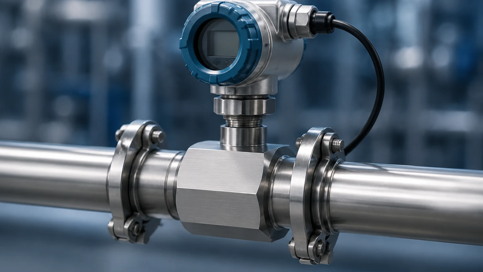
The performance of an inline pressure transmitter is heavily dependent on proper installation. Even the most accurate sensor will provide erroneous data if mounted incorrectly.
1. Orientation: For liquid applications, the transmitter should ideally be mounted on the side or bottom of the pipe to ensure the sensing element remains wetted and to prevent air pockets. For gas applications, mounting on the top of the pipe prevents condensate from accumulating on the diaphragm.
2. Isolation Valves: Always install a block-and-bleed valve or a manifold between the process and the transmitter. This allows for safe removal, calibration, and maintenance without shutting down the entire process line.
3. Venting: For gauge pressure transmitters, the back of the diaphragm must be vented to the atmosphere. Ensure the vent path is protected from moisture and dust ingress, often achieved through a vented cable or a specialized breather plug.
4. Impulse Lines: While inline transmitters are often direct-mounted, if impulse lines are used to stand the transmitter off from a hot process, they should be sloped (at least 1:12) to allow gas bubbles to escape or condensate to drain back into the process.
Limitations and Common Risks
While the inline pressure transmitter is a versatile tool, it is not without limitations. Engineers must be aware of the following risks:
* Pressure Spikes (Water Hammer): Rapid valve closures can create pressure surges that exceed the transmitter's overpressure limit. Using a pressure snubber can help dampen these spikes.
* Temperature Extremes: Standard transmitters have electronic components that can fail if exposed to temperatures above 85°C (185°F). For high-temperature applications, cooling elements or capillary-based remote seals may be necessary.
* Clogging and Buildup: In applications involving slurries or viscous fluids (like paper pulp or heavy crude), the small process port of a standard inline transmitter can clog. In these cases, a flush-diaphragm transmitter is a better choice as it eliminates the cavity where material can collect.
* Vacuum Conditions: Not all pressure transmitters are designed to handle vacuum. If a process involves vacuum cycles, ensure the sensor is rated for absolute pressure or specific vacuum ranges to prevent diaphragm damage.
Frequently Asked Questions (FAQ)
Q: How often should an inline pressure transmitter be calibrated?
A: Calibration frequency depends on the criticality of the process and the stability of the sensor. For most industrial applications, an annual calibration check is standard. However, in highly regulated industries like pharmaceuticals, semi-annual calibration may be required.
Q: Can I use an inline pressure transmitter for steam?
A: Yes, but you must protect the sensor from the high temperature. A common method is to use a pigtail syphon, which traps condensed water and acts as a thermal barrier between the steam and the transmitter.
Q: What is the difference between gauge and absolute pressure?
A: Gauge pressure is measured relative to the local atmospheric pressure. Absolute pressure is measured relative to a perfect vacuum. Inline transmitters for level measurement in open tanks are almost always gauge pressure types.
Final Project Confirmations
Before proceeding with the procurement of an inline pressure transmitter, project teams should confirm several key data points to ensure the selected instrument meets the application requirements:
* Confirm the maximum process temperature and pressure: Ensure the device is rated for the worst-case scenario, not just normal operating conditions.
* Verify electrical requirements: Confirm the available power supply (e.g., 24V DC) and the required input type for the control system.
* Assess environmental conditions: If the transmitter is installed outdoors, ensure it has an appropriate IP rating (IP65/IP67) and consider the impact of ambient temperature fluctuations on accuracy.
* Review chemical compatibility: Cross-reference the process medium with the wetted materials of the transmitter to prevent premature corrosion.
By following these guidelines and selecting high-quality instrumentation from reliable manufacturers, industrial operators can achieve long-term accuracy and reliability in their pressure and level measurement applications. For a broader overview of available technologies, including radar and ultrasonic alternatives, engineers are encouraged to consult the technical resources available on the Main Page.