Insertion Type Flow Meter
Insertion Type Flow Meter
In industrial process control, measuring the flow of liquids and gases in large-diameter piping presents significant logistical and financial challenges. While full-bore inline flow meters provide high accuracy, their cost and installation complexity increase exponentially with pipe size. The insertion type flow meter offers a versatile and cost-effective alternative, allowing for flow measurement by inserting a sensor probe directly into the flow stream through a single point of entry. This guide explores the engineering principles, selection criteria, and installation requirements for these instruments.
Measurement Principles of Insertion Flow Meters
Unlike full-bore meters that measure the entire cross-section of the fluid, an insertion type flow meter measures the fluid velocity at a specific point within the pipe. This "point velocity" is then used to calculate the volumetric flow rate based on the pipe's cross-sectional area and a calculated profile factor. The accuracy of this calculation depends heavily on the flow profile being fully developed and predictable.
Several sensing technologies are adapted for insertion applications:
1. Thermal Dispersion (Thermal Mass)
Thermal insertion meters utilize two sensors: one is heated, and the other measures the ambient temperature of the fluid. As gas flows past the heated sensor, it carries away heat. The electrical power required to maintain a constant temperature difference between the two sensors is directly proportional to the mass flow rate. This technology is primarily used for compressed air, nitrogen, and natural gas applications.
2. Electromagnetic (Magmeter)
Based on Faraday’s Law of Electromagnetic Induction, an insertion magmeter generates a magnetic field. As a conductive liquid (such as water or wastewater) flows through this field, it generates a voltage proportional to its velocity. This voltage is picked up by electrodes on the probe tip. These are ideal for large water distribution lines where shutting down the system for a full-bore installation is not feasible.
3. Turbine
Insertion turbine meters feature a small rotor at the end of the probe. The fluid velocity causes the rotor to spin at a speed proportional to the flow rate. A pickup coil or Hall effect sensor detects the rotation. While effective for clean liquids and gases, they are susceptible to mechanical wear and fouling from debris.
4. Vortex Shedding
These meters utilize a bluff body at the probe tip to create vortices in the fluid stream. The frequency at which these vortices are shed is directly proportional to the fluid velocity. Vortex meters are robust and suitable for steam, high-temperature gases, and low-viscosity liquids.
Key Evaluation and Selection Criteria
Selecting the correct insertion type flow meter requires an analysis of the fluid properties and the physical constraints of the piping system. For engineers evaluating measurement solutions for complex industrial environments, reviewing a wide range of instrumentation options on the Main Page can provide insights into how flow and level technologies integrate.
Fluid Characteristics
* Conductivity: Electromagnetic meters require a minimum conductivity (typically >5 μS/cm). For non-conductive fluids like oils or demineralized water, thermal or turbine meters are required.
* Viscosity: High-viscosity fluids can affect the flow profile and the mechanical performance of turbine meters. Vortex and thermal meters are generally preferred for low-viscosity applications.
* Cleanliness: Fluids with high solid content or fibrous material can wrap around turbine rotors or coat electrodes. In such cases, non-mechanical sensors like thermal or electromagnetic probes are superior.
Pipe Size and Material
Insertion meters are most advantageous in pipes larger than DN200 (8 inches). In smaller pipes, the probe itself can cause significant blockage, leading to pressure drops and measurement errors. The pipe material (carbon steel, stainless steel, PVC, or HDPE) determines the type of mounting hardware and welding requirements needed for the access port.
Performance Requirements
| Feature | Thermal Dispersion | Electromagnetic | Turbine | Vortex |
| :— | :— | :— | :— | :— |
| Primary Media | Gases | Conductive Liquids | Clean Liquids/Gases | Steam/Gases/Liquids |
| Typical Accuracy | ±1% to 2% of Reading | ±1% to 2% of Velocity | ±1% to 3% FS | ±1.5% to 2% of Reading |
| Pressure Drop | Negligible | Negligible | Low | Moderate |
| Moving Parts | None | None | Yes | None |
| Turndown Ratio | 100:1 | 10:1 to 20:1 | 10:1 | 10:1 to 15:1 |
Installation Considerations and the "Hot Tap" Advantage
The accuracy of an insertion type flow meter is highly sensitive to its installation. Because it only measures a single point in the flow stream, the velocity profile must be stable and symmetric.
Straight Pipe Requirements
To ensure a fully developed flow profile, the meter must be installed in a straight section of pipe. The standard recommendation is at least 10 to 20 diameters (10D–20D) of straight pipe upstream and 5 diameters (5D) downstream from any elbows, valves, or pumps. If these distances cannot be met, flow conditioners may be required, or the user must accept a higher margin of error.
Insertion Depth
The probe must be inserted to a specific depth to capture the representative velocity. In most turbulent flow regimes (Reynolds number > 4000), the sensor is typically positioned at the center of the pipe or at the 1/8th diameter point, depending on the manufacturer's calibration and the pipe size. Incorrect depth is the most common cause of measurement inaccuracy in insertion meters.
Hot Tapping
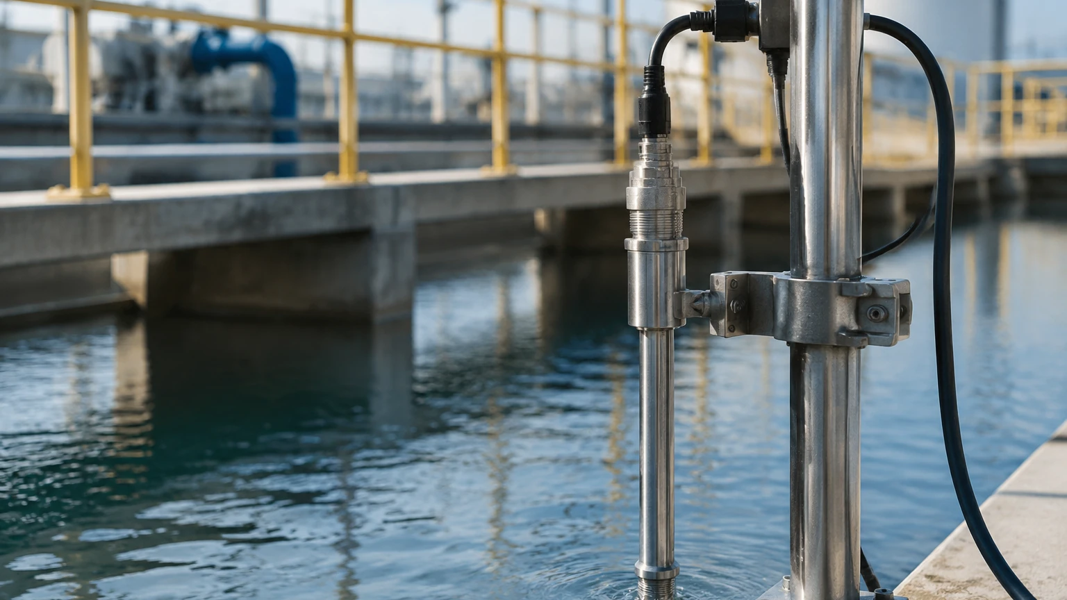
One of the primary benefits of insertion meters is the ability to perform a "hot tap" installation. This process involves welding a mounting boss (threadolet or flanged nozzle) onto the pipe, attaching a ball valve, and then using a specialized drilling machine to cut a hole in the pipe while it is under pressure. Once the hole is drilled, the probe is inserted through the valve. This eliminates the need for process shutdowns, making it the preferred method for retrofitting large industrial facilities.
Common Risks and Limitations
While versatile, insertion meters are not a universal solution. Engineers should be aware of the following risks:
1. Velocity Profile Sensitivity: If the flow is swirling or asymmetric due to nearby obstructions, a single-point measurement will be inaccurate. Multi-point insertion meters (probes with multiple sensors along their length) can mitigate this but at a higher cost.
2. Probe Vibration: In high-velocity applications, the probe can act as a cantilevered beam. If the fluid velocity matches the resonant frequency of the probe, it can lead to structural failure or excessive noise in the signal.
3. Blockage Ratio: In pipes smaller than DN100 (4 inches), the physical volume of the probe significantly reduces the cross-sectional area of the pipe, causing a local increase in velocity (the blockage effect) that must be compensated for mathematically.
4. Calibration Complexity: Unlike full-bore meters which are calibrated in a flow lab as a complete unit, insertion meters are often calibrated based on the probe's performance in a wind tunnel or small pipe, with the final accuracy dependent on the user's manual input of the actual pipe ID (Internal Diameter).
Maintenance and Troubleshooting FAQ
Q: How often should an insertion flow meter be calibrated?
A: For non-mechanical types like electromagnetic or thermal meters, an annual electronic verification is usually sufficient. Turbine meters may require more frequent physical inspection for bearing wear, especially in abrasive fluids.
Q: Can insertion meters be used for custody transfer?
A: Generally, no. Most custody transfer regulations require higher accuracy (±0.25% to ±0.5%) than what a point-velocity insertion meter can reliably provide. They are best suited for process monitoring, sub-metering, and efficiency tracking.
Q: What happens if the probe is not aligned with the flow?
A: Alignment is critical. Most probes have an alignment flat or arrow on the external housing. If the probe is rotated even 10 degrees away from the flow direction, the velocity reading can drop significantly, leading to under-reporting of flow.
Q: Is it possible to use these for steam measurement?
A: Yes, insertion vortex meters are commonly used for saturated and superheated steam. However, the materials of construction (seals and sensors) must be rated for the high temperatures and pressures associated with steam headers.
Conclusion
The insertion type flow meter remains a cornerstone of industrial efficiency, particularly for utilities and large-scale manufacturing. By providing a balance between cost and performance, it allows facilities to monitor previously unmeasured lines. Successful implementation requires strict adherence to straight-run requirements and precise insertion depth. For professionals seeking to optimize their process with reliable level and flow instrumentation, exploring technical specifications on the Main Page is a recommended next step to ensure the selected technology aligns with the specific demands of the application.