Liquid Flow Indicator
Liquid Flow Indicator
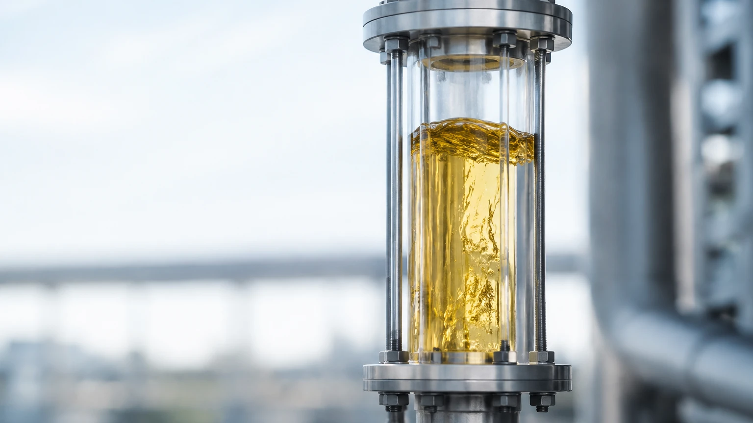
In the complex landscape of industrial process control, the ability to visually verify the movement and condition of fluids within a pipeline is a fundamental safety and operational requirement. A liquid flow indicator—often referred to as a sight flow indicator—is a device installed into a pipe to provide a visual window into the process. While advanced automated systems utilize electronic sensors to monitor flow rates and levels, the manual verification provided by a liquid flow indicator remains a critical secondary check for operators in water treatment, chemical processing, and oil and gas industries.
Integrating these indicators alongside high-precision instrumentation, such as those found on the Main Page of industrial measurement catalogs, ensures that automated data is backed by physical observation. This guide explores the principles, selection criteria, and technical considerations for implementing liquid flow indicators in industrial environments.
Principles of Visual Flow Monitoring
The primary function of a liquid flow indicator is to provide a real-time visual confirmation that flow is occurring, the direction of that flow, and the physical state of the fluid (such as color, clarity, or the presence of bubbles). Unlike flow meters that provide a numerical value, indicators are qualitative tools.
Mechanical Interaction
Most liquid flow indicators rely on the kinetic energy of the moving fluid to actuate a internal mechanical element. The most common mechanisms include:
* Flapper Style: A hinged flapper is pushed upward or forward by the force of the liquid. The angle of the flapper provides a rough estimation of the flow velocity. This is particularly useful for clear liquids where the flow might otherwise be invisible.
* Rotary/Paddle Wheel: The fluid strikes a rotor or paddle wheel, causing it to spin. The speed of rotation correlates with the flow rate. These are ideal for dark or opaque liquids where a flapper might be obscured, as the movement of the rotor edges is easier to detect.
* Ball/Drip Tube: In low-flow applications or vertical downward lines, a ball may be lifted by the fluid, or a drip tube may be used to observe falling droplets. This is common in lubrication systems and distillation processes.
Optical Transparency
The core component of any indicator is the viewing window. High-quality indicators utilize borosilicate glass, which offers superior thermal shock resistance and chemical durability compared to standard soda-lime glass. In high-pressure environments, these windows are often reinforced or doubled to prevent catastrophic failure.
Key Selection Criteria for Industrial Applications
Selecting the correct liquid flow indicator requires an analysis of the fluid properties and the mechanical constraints of the piping system. Failure to match the indicator to the process can lead to glass erosion, seal failure, or inaccurate readings.
1. Material Compatibility
The body of the indicator must withstand the corrosive nature of the fluid. Common materials include:
* Stainless Steel (304/316): Standard for food, beverage, and chemical industries due to corrosion resistance.
* Carbon Steel: Used in oil and gas applications where corrosion is less of a concern but high strength is required.
* PVC/PP: Utilized in water treatment or low-temperature acid lines where metallic contamination must be avoided.
2. Pressure and Temperature Ratings
Flow indicators are often the "weak link" in a high-pressure system due to the glass component. It is essential to verify that the unit is rated for the maximum operating pressure (measured in bar or PSI) and temperature (Celsius or Fahrenheit). For temperatures exceeding 150°C, specialized gaskets and tempered borosilicate glass are mandatory.
3. Connection Type
Indicators are typically integrated into the line via:
* Threaded Connections (NPT/G): Common for smaller pipes (15 mm to 50 mm).
* Flanged Connections (ANSI/DIN): Required for larger industrial lines (50 mm to 300 mm+) to ensure leak-proof seals and ease of maintenance.
Technical Comparison of Indicator Types
| Indicator Type | Best For | Flow Direction | Visibility | Pressure Drop |
| :— | :— | :— | :— | :— |
| Double Window | General Purpose | Horizontal/Vertical Up | High | Low |
| Tubular | Low Pressure | Any | 360-degree | Negligible |
| Flapper | Clear Liquids | Horizontal/Vertical Up | Moderate | Low |
| Paddle Wheel | Opaque/Dark Fluids | Any | High | Moderate |
| Drip Tube | Very Low Flow | Vertical Down | High | Low |
Installation and Engineering Considerations
Proper installation is vital for both the longevity of the liquid flow indicator and the safety of the personnel monitoring it. Unlike a radar level meter, which may be mounted at the top of a tank, a flow indicator must be placed where it is easily accessible to the human eye.
Orientation and Flow Direction
Not all indicators are bi-directional. Flapper-style indicators usually require a specific orientation (typically horizontal or vertical-up) to ensure gravity returns the flapper to the closed position when flow stops. Paddle wheel indicators are generally more flexible regarding orientation but should be installed in a section of pipe that is always full of liquid to prevent erratic spinning.
Safety Shielding
In applications involving hazardous chemicals or high-pressure steam, a transparent safety shield (polycarbonate or metal mesh) should be installed over the glass window. This protects operators from potential glass shards or fluid spray in the event of a window rupture.
Turbulence and Pipe Runs
To ensure a steady visual representation, indicators should ideally be placed at least five pipe diameters away from pumps, valves, or elbows. Excessive turbulence can cause mechanical fatigue in flappers and rotors, leading to premature failure of internal pins and bearings.
Limitations and Operational Risks
While highly effective for visual monitoring, the liquid flow indicator has inherent limitations that engineers must account for:
1. Fouling and Scaling: In untreated water or heavy oil applications, the glass window can become coated with scale or debris. This obscures the view and requires the system to be bypassed or shut down for cleaning.
2. Pressure Surges: Sudden spikes in pressure (water hammer) can shatter the glass components. Installing surge suppressors or choosing "armored" sight glasses can mitigate this risk.
3. Mechanical Wear: Moving parts like rotors and flappers are subject to wear over time. If a rotor breaks loose, it can travel downstream and damage sensitive equipment like turbines or high-precision level sensors. Regular inspection of internal components is necessary.
4. No Data Logging: A standard indicator does not provide an electronic signal. For integrated automation, it must be used in conjunction with electronic flow transmitters or level measurement solutions available on the Main Page.
Frequently Asked Questions (FAQ)
Q: Can a liquid flow indicator be used for gases?
A: While specifically designed for liquids, many flapper and rotary indicators can be used for gas flow, provided the gas velocity is sufficient to move the internal mechanism and the pressure ratings are strictly observed. However, specialized gas indicators are usually recommended.
Q: How often should the glass be replaced?
A: There is no fixed interval, but glass should be inspected during every maintenance cycle. If there are signs of thinning (due to erosion), scratching, or chemical etching (cloudiness that cannot be wiped off), the glass must be replaced immediately.
Q: What is the difference between a sight glass and a flow indicator?
A: A sight glass is a simple window used to see the contents of a tank or pipe (often used for level checking). A liquid flow indicator includes an internal mechanism (like a flapper or rotor) specifically designed to show the *movement* of the fluid.
Q: Are there indicators suitable for hygienic/sanitary applications?
A: Yes. Sanitary indicators are made with polished 316L stainless steel and use USP Class VI gaskets (like EPDM or Silicone) to ensure there are no crevices where bacteria can grow. These are common in the pharmaceutical and dairy industries.
Conclusion
The liquid flow indicator serves as a vital bridge between automated sensor data and manual process verification. By providing a direct window into the pipeline, it allows operators to confirm pump operation, detect pipe blockages, and observe fluid quality changes that electronic sensors might miss. When selecting an indicator, engineers must prioritize material compatibility, pressure ratings, and the specific visibility needs of the fluid in question. For comprehensive process control, combining visual indicators with robust level measurement technology ensures a redundant and safe industrial operation. For more information on professional-grade measurement instruments, users are encouraged to review the technical specifications on the Main Page of leading industrial suppliers.