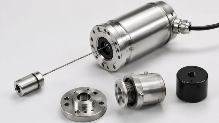
Instrument Calibrations
Instrument Calibrations
In the landscape of industrial automation, instrument calibrations serve as the foundational process for ensuring that measurement data remains accurate, reliable, and traceable. For level measurement instruments—ranging from radar and ultrasonic sensors to hydrostatic transmitters and magnetic gauges—calibration is the act of comparing the instrument's output against a known standard of higher accuracy. This process identifies and corrects deviations, ensuring that the level readings used for inventory management, process control, and safety interlocks are within specified tolerances.
Accurate level measurement is critical in sectors such as water treatment, chemical processing, and oil and gas. Without regular instrument calibrations, sensor drift, environmental factors, and component aging can lead to measurement errors. These errors can result in tank overflows, pump cavitation, or inefficient chemical dosing. This guide explores the principles of level measurement, the methodologies for calibration, and the technical considerations necessary for maintaining high-performance instrumentation.
Measurement Principles and Calibration Requirements
Before implementing a calibration schedule, it is essential to understand the underlying physical principles of the instruments being serviced. Different technologies interact with the process media in unique ways, necessitating specific calibration approaches.
Radar Level Meters
Radar level meters utilize electromagnetic waves, typically in the microwave frequency range. The instrument emits a signal that reflects off the surface of the medium and returns to the sensor. The distance is calculated using the Time of Flight (ToF) principle. Calibration for radar involves defining the "Zero" point (empty tank) and the "Span" (full tank). Because radar is sensitive to the dielectric constant of the material and internal tank obstructions, instrument calibrations often include mapping out false echoes to ensure the sensor ignores reflections from agitators or internal pipes.
Ultrasonic Level Sensors
Similar to radar, ultrasonic sensors use ToF but rely on sound waves. The speed of sound is highly dependent on air temperature and composition. Therefore, calibration for ultrasonic devices frequently involves temperature compensation. Calibrating these units requires verifying that the sensor correctly interprets the return signal across the entire measurement range, particularly in the "dead zone" near the sensor face where measurements are not possible.
Hydrostatic Level Transmitters
Hydrostatic sensors measure the pressure exerted by a liquid column. The relationship is defined by the formula $P = \rho gh$, where $P$ is pressure, $
ho$ is the density of the liquid, $g$ is gravity, and $h$ is the height of the liquid. Instrument calibrations for hydrostatic transmitters are density-dependent. If the process fluid density changes due to temperature fluctuations or chemical composition shifts, the transmitter must be recalibrated to reflect the new density to maintain height accuracy.
Magnetic Level Gauges and Switches
These mechanical-electrical hybrids use a float containing a magnet to actuate external indicators or switches. Calibration involves verifying the buoyancy of the float relative to the liquid's specific gravity and ensuring the magnetic coupling triggers the reed switches or transmitters at the precise physical points required by the process logic.
Common Methods for Performing Instrument Calibrations
Instrument calibrations can be categorized based on the environment and the method of verification used. The choice of method often depends on the criticality of the measurement and the accessibility of the tank.
1. Dry Calibration (Bench Calibration): This is performed in a laboratory or workshop before the instrument is installed. A simulator or a known physical distance is used to mimic the level. For pressure-based sensors, a deadweight tester or a precision pressure calibrator is used to apply known pressures to the sensing element.
2. Wet Calibration (Field Calibration): This occurs while the instrument is installed in the tank. The tank level is physically changed to specific reference points (e.g., 25%, 50%, 75%, and 100%). The instrument's output is then compared to a manual measurement, such as a sounding tape or a sight glass. This is the most accurate method for reflecting real-world process conditions.
3. Standard Reference Calibration: This involves using a secondary, high-precision portable instrument to verify the readings of the permanently installed sensor. This method is common for non-contact sensors like radar where changing the tank level is not logistically feasible.
Selection Criteria for Level Measurement Technologies
Choosing the right instrument and understanding its calibration needs is vital for long-term operational success. Engineers should evaluate instruments based on the following criteria:
| Technology | Accuracy | Calibration Frequency | Best Application |
| :— | :— | :— | :— |
| Radar (Guided/Non-contact) | High (±1mm to ±5mm) | Low | Corrosive liquids, high pressure, vacuum |
| Ultrasonic | Moderate (±0.25% of range) | Medium | Open channels, water tanks, solids |
| Hydrostatic | High (±0.1% to ±0.5% span) | Medium | Deep wells, vented tanks, constant density |
| Magnetic Gauge | Moderate (±5mm to ±10mm) | Low | High-temperature boilers, visual indication |
| Level Switches | Point Detection | Periodic Testing | Overfill protection, pump control |
When evaluating these technologies for specific industrial automation needs, users often Review product options and application support to ensure the selected hardware aligns with the required calibration intervals and environmental constraints.
Installation Best Practices to Maintain Calibration Integrity
The physical installation of an instrument significantly impacts how often instrument calibrations are required and how much the device will drift over time. Even a perfectly calibrated sensor will provide false data if installed incorrectly.
* Avoid Turbulence and Foam: For ultrasonic and radar sensors, foam can absorb signals, while turbulence can cause erratic readings. Installing the sensor in a stilling well or a bypass chamber can provide a calm surface for more stable calibration.
* Nozzle Geometry: Ensure that the mounting nozzle does not interfere with the signal beam. For radar, the nozzle should be short enough that the beam expands beyond the nozzle edge before hitting the tank walls.
* Mounting Position: Hydrostatic transmitters should be mounted at a point where sediment cannot accumulate on the diaphragm. If mounted on a side wall, the "Zero" point must account for the vertical distance between the sensor and the tank bottom (zero offset).
* Environmental Shielding: Extreme temperature fluctuations can cause thermal expansion in mechanical components or electronic drift. Sunshades and insulation help maintain the thermal stability of the instrument electronics.

Limitations and Factors Affecting Accuracy
No instrument is immune to error. Understanding the limitations of instrument calibrations helps in troubleshooting and setting realistic expectations for process control.
* Media Build-up: In chemical or wastewater applications, material can coat the sensor face or the float. This build-up changes the signal characteristics and may require the instrument to be cleaned before a valid calibration can be performed.
* Ambient Interference: For ultrasonic sensors, high-speed air currents or heavy vapors can change the speed of sound, leading to distance errors. Radar sensors may be affected by heavy steam or dust if the dielectric constant of the air changes significantly.
* Hysteresis and Linearity: All electronic instruments have a degree of hysteresis (the difference in readings when approaching a point from above vs. below). Calibration procedures should include both upscale and downscale checks to identify these non-linearities.
* Power Supply Stability: Fluctuations in the 24V DC loop power can introduce noise into the 4-20mA signal, appearing as calibration drift. Ensuring a regulated power supply is a prerequisite for accurate instrument calibrations.
Practical Calibration Checklist
To ensure a successful calibration event, technical teams should follow a standardized checklist:
1. Safety Clearance: Ensure the tank is in a safe state and all automated control loops are switched to "Manual" mode to prevent accidental valve movements.
2. Visual Inspection: Check for physical damage, corrosion, or moisture ingress in the terminal housing.
3. Zero Verification: Confirm the instrument reads zero (or 4mA) when the tank is empty or at the minimum reference level.
4. Span Verification: Confirm the instrument reads 100% (or 20mA) when the tank is at the maximum working level.
5. Multi-point Check: Test at 25%, 50%, and 75% to ensure linearity across the entire range.
6. Documentation: Record the "As-Found" and "As-Left" data. This documentation is essential for regulatory compliance and for tracking the stability of the instrument over time.
Frequently Asked Questions
Q: How often should instrument calibrations be performed?
A: The frequency depends on the criticality of the process and the manufacturer's recommendations. Typically, level instruments are calibrated annually. However, in high-safety applications (SIL-rated loops), semi-annual or quarterly checks may be required.
Q: Can I calibrate a radar level meter without emptying the tank?
A: Yes, this is known as "dry calibration" or "mapping." Using the manufacturer's software, you can input the tank dimensions and dielectric properties. However, a "wet" check at a known level is always recommended to verify the configuration.
Q: What is the difference between calibration and configuration?
A: Configuration involves setting the parameters of the device (e.g., units of measure, tank height, output type). Calibration is the physical process of verifying and adjusting the accuracy of the measurement against a standard.
Q: Why does my hydrostatic transmitter show a level when the tank is empty?
A: This is usually due to a zero-shift caused by the weight of the liquid in the impulse lines (wet leg) or atmospheric pressure changes if the tank is sealed but the transmitter is vented to the atmosphere. A zero-trim during instrument calibrations will correct this.
Q: Does temperature affect magnetic level gauges?
A: Yes. While the magnetic coupling is generally stable, the density of the liquid changes with temperature. If the liquid becomes less dense as it heats up, the float will sit lower in the liquid, potentially causing a slight under-read of the actual level.
By adhering to rigorous instrument calibrations protocols and selecting the appropriate technology for the specific environment, industrial facilities can ensure long-term accuracy and safety in their level measurement applications. For those seeking to upgrade their current systems or source new measurement hardware, the Main Page offers a comprehensive overview of modern industrial solutions designed to minimize maintenance and maximize precision.