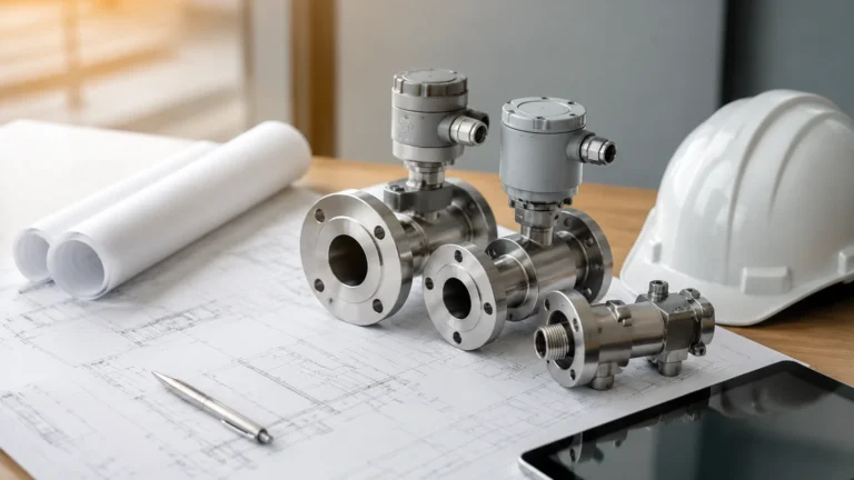
Io Link Sensor
Io Link Sensor
In the era of Industry 4.0 and the Industrial Internet of Things (IIoT), the demand for transparent data and seamless communication between the field level and the control level has never been higher. The IO-Link sensor has emerged as a pivotal technology in meeting these demands, particularly within the field of industrial level measurement. As a standardized, point-to-point communication protocol (IEC 61131-9), IO-Link allows for the bidirectional exchange of data between sensors and an IO-Link master, which then transmits that information to the higher-level PLC or ERP system.
For engineers and system integrators, transitioning from traditional 4-20mA analog signals to an IO-Link sensor ecosystem offers significant advantages in terms of configuration, diagnostics, and maintenance. This guide explores the principles of IO-Link technology, its application in level measurement, and the critical factors to consider when selecting and installing these devices.
Understanding the IO-Link Principle
To appreciate the value of an IO-Link sensor, one must first understand how the communication layer operates. Unlike traditional fieldbuses, IO-Link is not a bus system but a powerful point-to-point communication link. It utilizes standard, non-shielded three-wire cables, typically terminating in M12, M8, or M5 connectors.
The Communication Architecture
An IO-Link system consists of three primary components:
1. IO-Link Master: The gateway between the sensors and the higher-level fieldbus (such as PROFINET, EtherNet/IP, or Modbus TCP).
2. IO-Link Device: The sensor (e.g., a radar level meter or ultrasonic sensor) that performs the actual measurement.
3. Unshielded 3-wire Cable: The physical medium that carries power (24V) and the digital signal (C/Q line).
Data Types Transmitted
An IO-Link sensor transmits four types of data:
* Process Data: The actual measurement value (e.g., level in millimeters or pressure in bar). This is sent cyclically at high speeds.
* Value Status: Indicates whether the process data is valid or if an error has occurred.
* Device Parameters: Acyclic data such as sensitivity settings, measurement range, and damping filters. These can be written to the sensor from the PLC.
* Events/Diagnostics: Error messages, maintenance warnings (e.g., lens fouling on a radar sensor), and device status updates.
Level Measurement Technologies with IO-Link Integration
Level measurement is a critical process in water treatment, chemical processing, and oil and gas industries. Integrating an IO-Link sensor into these applications allows for more granular control over the measurement process. Below are the primary technologies utilized by Welk that benefit from IO-Link connectivity.
Radar Level Meters
Radar sensors utilize Time-of-Flight (ToF) principles, emitting high-frequency microwave pulses that reflect off the surface of the medium. By measuring the time it takes for the pulse to return, the sensor calculates the distance. When equipped with IO-Link, a radar sensor can provide not just the level, but also the signal strength (echo quality), which helps in predicting when the sensor might need cleaning or realignment.
Ultrasonic Level Sensors
Similar to radar, ultrasonic sensors use sound waves. They are cost-effective for open-channel flow and wastewater applications. An IO-Link-enabled ultrasonic sensor can transmit internal temperature data to the PLC, allowing for more accurate sound-velocity compensation and improved precision in fluctuating environments.
Hydrostatic Level Transmitters
These sensors measure the pressure exerted by a liquid column. In an IO-Link configuration, the user can remotely adjust the density parameters of the liquid via the PLC. This is particularly useful in chemical tanks where the medium might change, eliminating the need for manual recalibration at the tank site.
Key Benefits of IO-Link Sensors in Industrial Applications
1. Simplified Installation and Wiring
Traditional analog sensors often require shielded cables to prevent electromagnetic interference (EMI) from distorting the 4-20mA signal. An IO-Link sensor uses digital transmission, which is inherently more robust against noise. This allows for the use of standard, inexpensive unshielded cables, significantly reducing installation costs.
2. Remote Parameterization
One of the most significant advantages is the ability to configure sensors from the control room. If a process change requires a different measurement range or a change in the switching point of a level switch, the parameters can be downloaded to the sensor via the IO-Link master. This eliminates the need for technicians to access sensors located in hard-to-reach or hazardous areas.
3. Automatic Device Replacement
When an IO-Link sensor needs replacement, the IO-Link master can automatically recognize the new device and upload the previous sensor's configuration. This "plug-and-play" functionality minimizes downtime and ensures that the new sensor is configured exactly like the old one, reducing the risk of human error during setup.
4. Enhanced Diagnostics and Predictive Maintenance
IO-Link sensors provide a wealth of diagnostic data. For instance, a level sensor can report its internal temperature or the number of operating hours. If the signal quality drops below a certain threshold—perhaps due to foam buildup or condensation—the sensor sends an "Event" to the PLC. This allows maintenance teams to address the issue before the sensor fails completely.
Selection Criteria for IO-Link Level Sensors
Selecting the right IO-Link sensor requires a thorough understanding of the process environment and the communication requirements. Use the following table as a reference for comparing different level measurement technologies in an IO-Link context.
Selection Table: IO-Link Level Measurement Technologies
| Feature | Radar (80GHz) | Ultrasonic | Hydrostatic | Magnetic Level Gauge |
| :— | :— | :— | :— | :— |
| Accuracy | ±2 mm | ±0.2% of range | ±0.1% to 0.5% | ±5 mm to 10 mm |
| Measurement Range | Up to 30m (or 120m) | 0.1m to 15m | 1m to 200m H2O | Up to 6m |
| Medium Compatibility | Liquids, solids, corrosive | Liquids, wastewater | Liquids only | Liquids (clean) |
| Pressure Limits | Up to 4.0 MPa | Atmospheric | Up to 10 MPa | Up to 16 MPa |
| IO-Link Benefit | Signal quality tracking | Temp compensation | Remote density adjust | Digital switch points |
| Typical Application | Chemical tanks, silos | Sump pits, flumes | Deep wells, reservoirs | Boiler level, fuel tanks |
Communication Speed (COM1, COM2, COM3)
When selecting an IO-Link sensor, check its supported transmission rate:
* COM1: 4.8 kbit/s
* COM2: 38.4 kbit/s (Most common for level sensors)
* COM3: 230.4 kbit/s (Used for high-speed or high-data-volume sensors)
Most level measurement applications are well-served by COM2, as level changes are generally slow compared to motion control applications.
Installation and Configuration Considerations
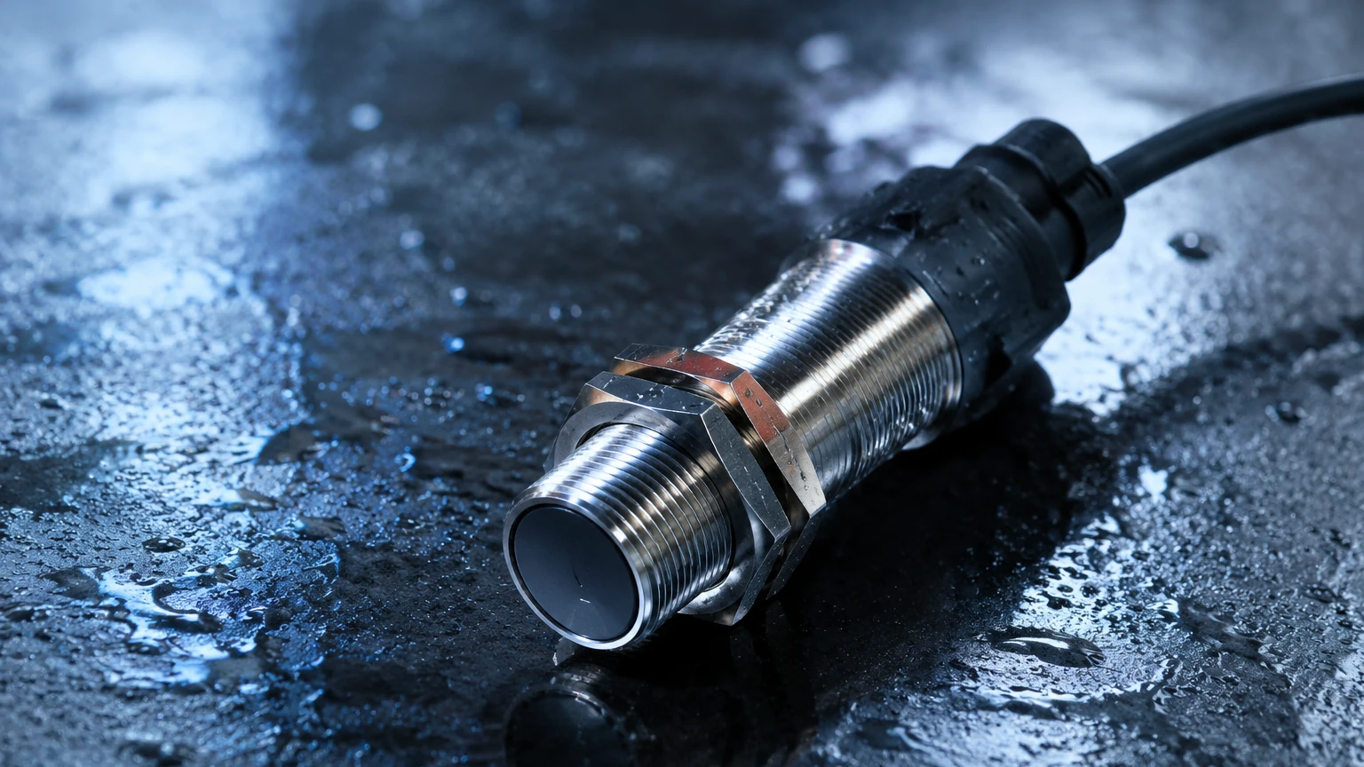
To ensure reliable performance of an IO-Link sensor, follow these engineering best practices:
Cable Length Limitations
The IO-Link standard specifies a maximum cable length of 20 meters between the sensor and the IO-Link master. If the distance from the tank to the control cabinet exceeds 20 meters, the IO-Link master should be placed in a field-mounted junction box closer to the process, with a high-level fieldbus (like PROFINET) carrying the data back to the PLC.
IODD Files
Every IO-Link sensor comes with an IODD (I/O Device Description) file. This file contains all the information about the device's parameters, identification, and communication properties. Before commissioning, ensure the IODD file is uploaded to the IO-Link master's configuration tool. This allows the software to display the sensor's data in a human-readable format.
Port Configuration
IO-Link master ports can often be configured in different modes:
* IO-Link Mode: For bidirectional digital communication.
* DI Mode: The port acts as a standard digital input.
* DQ Mode: The port acts as a standard digital output.
Ensure the port is correctly set to "IO-Link" to enable the advanced features of the sensor.
Limitations of IO-Link Sensors
While highly versatile, IO-Link is not a universal solution for every application:
* Data Bandwidth: IO-Link is not designed for transmitting large files or high-resolution video. It is optimized for process data and parameters.
* Distance: The 20m limit is a strict physical layer constraint. For very large tank farms, this requires a decentralized I/O architecture.
* Power Consumption: Most IO-Link ports provide a limited amount of current (typically up to 200mA). Ensure the sensor's power requirements, especially for heated probes or high-power radar, do not exceed the master's port capacity.
Frequently Asked Questions (FAQs)
Q: Can I use an IO-Link sensor with a standard digital input card?
A: Yes, most IO-Link sensors support a "SIO Mode" (Standard I/O). In this mode, the C/Q line acts as a traditional switching output. However, you will lose all the digital diagnostic and parameterization benefits.
Q: Do I need special cables for IO-Link?
A: No. One of the primary benefits is that you can use standard, unshielded M12 cables. This is a major cost-saving over the shielded cables required for high-precision analog signals.
Q: How does IO-Link handle electromagnetic interference (EMI)?
A: Because the signal is digital (24V pulses), it has a much higher signal-to-noise ratio than a 4-20mA current loop. This makes it very resistant to EMI in industrial environments.
Q: Can I connect multiple sensors to a single IO-Link port?
A: No, IO-Link is a point-to-point connection. Each sensor requires its own port on the IO-Link master. However, a single master typically has 4 to 8 ports.
Conclusion
The adoption of the IO-Link sensor in level measurement represents a significant step toward more intelligent and manageable industrial processes. By providing a bridge between the physical measurement and the digital world, IO-Link enables predictive maintenance, reduces installation costs, and simplifies device management. Whether you are monitoring water levels in a municipal reservoir or managing complex chemical inventories, IO-Link provides the data transparency needed for modern automation.
For more information on selecting the right level measurement technology for your specific application, you can Review product options and application support on our Main Page. Selecting the right instrument involves balancing accuracy, environmental conditions, and integration requirements, and our team is ready to assist in providing reliable, cost-effective solutions.