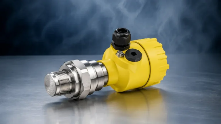
Knockout Drum
Knockout Drum
In industrial process engineering, the knockout drum—often referred to as a liquid-gas separator or a flare seal drum—serves as a critical safety and operational component. Its primary function is to remove entrained liquid droplets from a gas stream. This process is vital for protecting downstream equipment, such as compressors, from liquid slugging and ensuring that flare systems operate safely by preventing liquid carryover into the atmosphere.
Reliable level measurement within a knockout drum is not merely a matter of process efficiency; it is a fundamental safety requirement. If the liquid level in a knockout drum rises too high, the separation efficiency drops, leading to "carryover" where liquids enter gas lines. Conversely, failing to monitor the lower limits can lead to gas blow-by in liquid discharge lines. This guide explores the engineering principles of level measurement in knockout drums and provides a framework for selecting the most appropriate instrumentation.
Principles of Operation in a Knockout Drum
A knockout drum operates on the principle of gravity separation. As a high-velocity gas stream enters the larger volume of the drum, its velocity decreases significantly. This drop in velocity allows liquid droplets, which are denser than the gas, to fall out of the suspension and collect at the bottom of the vessel. In many designs, internal components such as mist eliminators or baffle plates are used to coalesce smaller droplets into larger ones, further enhancing separation.
Because the knockout drum is often the last line of defense before a flare or a compressor, the level instrumentation must be capable of operating under a wide range of conditions, including varying pressures, temperatures, and fluid densities. Understanding the physics behind the measurement is the first step in selecting the right tool for the job.
Time-of-Flight (ToF) Measurement
This principle is used by radar and ultrasonic sensors. A signal is emitted from the top of the vessel, reflects off the liquid surface, and returns to the sensor. By measuring the time taken for this round trip, the device calculates the distance to the liquid surface. In a knockout drum, radar is generally preferred over ultrasonic due to the presence of vapors or pressure changes that can affect the speed of sound.
Buoyancy (Archimedes' Principle)
Used by magnetic level gauges and float switches, this principle relies on a float that is weighted to match the density of the process liquid. As the liquid level in the knockout drum rises, the float moves, providing either a visual indication or triggering a switch. This is a mechanical, highly reliable method that does not require power for basic visual monitoring.
Hydrostatic Pressure
This method measures the pressure exerted by the liquid column. The pressure at the bottom of the drum is proportional to the height of the liquid and its density. While common, this method requires accurate knowledge of the fluid's specific gravity, which can be a challenge if the knockout drum collects a mixture of different hydrocarbons and water.
Technology Recommendations for Knockout Drums
Selecting the right instrument depends on the specific process conditions of the knockout drum. Below are the primary technologies utilized in modern industrial applications.
Guided Wave Radar (GWR)
Guided Wave Radar is often considered the "gold standard" for knockout drum level measurement. It utilizes a probe (waveguide) that extends into the liquid. High-frequency microwave pulses travel down the probe, reflect off the liquid surface, and return.
* Advantages: GWR is unaffected by changes in gas composition, pressure, or temperature. It is also highly effective in vessels with internal obstructions or where foam may be present on the liquid surface.
* Limitations: The probe is in contact with the process fluid, meaning it must be compatible with the chemical properties of the collected liquids.
Non-Contact Radar
For applications where the liquid is highly corrosive or where a probe cannot be inserted, non-contact radar (typically 80GHz) is an excellent alternative. It measures the level through the vapor space without touching the liquid.
* Advantages: Zero maintenance regarding the wetted parts and easy to install on existing nozzles.
* Limitations: Can be affected by heavy foam or extremely low dielectric constant liquids, though modern high-frequency radars have largely mitigated these issues.
Magnetic Level Gauges (MLG)
In many knockout drum installations, a magnetic level gauge is mounted on the side of the vessel as a bypass chamber. A float containing a magnet moves with the liquid level, flipping external flags to provide a clear visual indication.
* Advantages: Provides a clear visual level without requiring power. It can be equipped with reed switches or transmitters for remote monitoring.
* Limitations: Not suitable for extremely viscous liquids that might cause the float to stick.
Selection Criteria for Knockout Drum Instrumentation
When evaluating instrumentation for a knockout drum, engineers should use the following criteria to ensure long-term reliability:
| Criteria | Guided Wave Radar | Non-Contact Radar | Magnetic Level Gauge | Hydrostatic Transmitters |
| :— | :— | :— | :— | :— |
| Accuracy | High (±2mm) | High (±1mm) | Moderate | Moderate |
| Pressure Range | Up to 400 bar | Up to 160 bar | Up to 250 bar | Varies by sensor |
| Temperature | Up to 450°C | Up to 200°C | Up to 400°C | Up to 120°C |
| Foam Handling | Excellent | Moderate | Good | Not Applicable |
| Maintenance | Low | Very Low | Low | Moderate |
| Reliability | Very High | High | Very High | Moderate |
For a comprehensive overview of available technologies and specific model specifications, engineers are encouraged to visit the Main Page of our technical catalog.
Installation Considerations
The performance of any level meter in a knockout drum is heavily dependent on proper installation. The following factors must be addressed during the design phase:
1. Nozzle Placement: The measurement nozzle should be located away from the inlet stream to avoid turbulence and false readings caused by the incoming gas/liquid mixture.
2. Stilling Wells and Bypass Chambers: For radar applications where the surface may be turbulent, a stilling well (internal pipe) or a bypass chamber (external pipe) is recommended to provide a calm surface for measurement.
3. Dead Zones: Every radar or ultrasonic sensor has a "dead zone" or "blocking distance" near the antenna where measurement is not possible. Ensure the nozzle height and vessel geometry account for this to prevent missing a high-level alarm.
4. Venting and Draining: For bypass chambers and magnetic level gauges, ensure proper vent and drain valves are installed to allow for maintenance and calibration without shutting down the entire process.

Limitations and Common Risks
While modern instrumentation is highly advanced, certain risks remain inherent to knockout drum applications:
* Paraffin or Wax Buildup: In oil and gas applications, heavy hydrocarbons may solidify or leave deposits on probes and floats. This requires periodic cleaning or the use of specialized coatings.
* Dielectric Changes: If the knockout drum collects liquids with very low dielectric constants (e.g., liquid propane), the reflection signal for radar may be weak. In these cases, GWR with a coaxial probe is usually the best solution.
* Vapor Phase Compensation: In high-pressure steam or hydrocarbon applications, the gas density can change the speed of the radar signal. High-end GWR units include gas phase compensation to maintain accuracy.
Frequently Asked Questions (FAQ)
Q: How often should knockout drum level sensors be calibrated?
A: For safety-critical applications like flare knockout drums, a proof test and calibration check should be performed annually. However, non-contact radar systems often require less frequent calibration compared to mechanical or hydrostatic systems.
Q: Can one sensor handle both oil and water levels?
A: Yes, Guided Wave Radar is capable of measuring both the total level and the interface level (the point where oil sits on top of water) simultaneously, provided there is a sufficient difference in the dielectric constants of the two liquids.
Q: What is the risk of using a standard float switch in a knockout drum?
A: Standard float switches can be prone to mechanical failure if the liquid is corrosive or if debris is present in the drum. For safety-critical high-high (HH) alarms, redundant technologies (e.g., a vibrating fork switch alongside a radar transmitter) are recommended.
Q: Do I need a SIL-rated instrument for my knockout drum?
A: If the knockout drum is part of a Safety Instrumented System (SIS) to prevent environmental discharge or equipment damage, SIL2 or SIL3 rated instruments are typically required by industry safety standards (IEC 61508/61511).
Conclusion
The knockout drum is a vital safeguard in industrial processing, and its effectiveness is directly tied to the accuracy of its level measurement. By understanding the principles of radar, buoyancy, and pressure, and by matching these technologies to the specific pressures and temperatures of the process, engineers can ensure both safety and operational continuity. For further technical support and product selection, consult the resources available on our Main Page.