Silo Measurement Systems
Silo Measurement Systems
In industrial bulk storage, silo measurement systems are essential components for inventory management, process efficiency, and operational safety. Silos are used across diverse sectors—from cement production and grain processing to chemical manufacturing and water treatment—to store large volumes of solids, powders, or liquids. Unlike standard tank gauging, measuring levels in a silo presents unique challenges, including heavy dust, uneven material surfaces, and internal structural obstructions.
Selecting the appropriate technology requires an understanding of the material properties, the physical dimensions of the silo, and the environmental conditions within the vessel. As a professional manufacturer, Welk provides a range of instruments designed to address these complexities, ensuring that operators have access to real-time, accurate data for their Main Page of industrial automation and supply chain logistics.
Understanding Silo Measurement Technologies
Silo measurement systems generally fall into two categories: continuous level measurement and point level detection. Continuous systems provide a constant reading of the material level, usually expressed as a percentage of volume or a specific height in meters. Point level detection, facilitated by level switches, acts as a safety mechanism to prevent overfilling or to signal when a silo is nearly empty.
Modern industrial facilities increasingly rely on non-contact technologies, such as radar and ultrasonic sensors, because they reduce maintenance requirements by eliminating physical contact with potentially abrasive or corrosive materials. However, contact-based methods like guided wave radar (GWR) or electromechanical "plumb bob" systems remain relevant in specific applications where material dielectric constants are extremely low or where heavy foam is present.
Key Measurement Principles
Before selecting a system, it is vital to understand the physics behind the most common measurement principles used in silos.
Radar Level Measurement (FMCW)
Frequency Modulated Continuous Wave (FMCW) radar is the gold standard for modern silo measurement systems. These sensors emit a continuous high-frequency signal (often in the 26 GHz or 80 GHz range) that increases in frequency over time. The signal reflects off the material surface and returns to the sensor. By measuring the frequency difference between the emitted and received signals, the device calculates the distance with high precision.
* Advantages: 80 GHz radar offers a narrow beam angle, which is critical for avoiding internal silo structures like ladders or agitators. It is unaffected by dust, pressure, or temperature fluctuations.
* Limitations: Highly dependent on the reflective properties (dielectric constant) of the material.
Ultrasonic Level Measurement
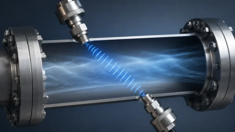
Ultrasonic sensors function by emitting high-frequency sound pulses. The time it takes for the pulse to travel to the surface and back (Time-of-Flight) determines the distance.
* Advantages: Cost-effective and easy to install for liquid silos or solids with minimal dust.
* Limitations: Sound waves are easily attenuated by heavy dust clouds or acoustic-absorbing materials (like fine powders). They are also sensitive to air temperature changes, which affect the speed of sound.
Guided Wave Radar (GWR)
GWR utilizes a probe (cable or rod) that extends to the bottom of the silo. A low-energy microwave pulse travels along the probe, reflects off the material surface, and returns.
* Advantages: Excellent for materials with low dielectric constants or where the surface is turbulent. The signal is focused along the probe, minimizing interference from silo walls.
* Limitations: The probe is subject to mechanical stress from heavy solids (pull-down forces) and can be damaged during silo discharge.
Selecting the Right Silo Measurement System
Choosing between technologies depends on the specific characteristics of the stored medium and the silo's physical environment. The following table provides a comparison based on common industrial criteria:
| Criteria | 80 GHz Radar | Ultrasonic | Guided Wave Radar | Hydrostatic (Liquids Only) |
| :— | :— | :— | :— | :— |
| Accuracy | ±1 mm to ±2 mm | ±0.25% of range | ±2 mm | ±0.1% to ±0.5% |
| Dust Resistance | Excellent | Poor | Good | N/A |
| Max Range | Up to 120m (393 ft) | Up to 30m (98 ft) | Up to 75m (246 ft) | Dependent on Pressure |
| Material State | Solids & Liquids | Liquids & Some Solids | Solids & Liquids | Liquids Only |
| Maintenance | Very Low | Low | Moderate (Probe wear) | Moderate (Sensor cleaning) |
| Cost | High | Low to Moderate | Moderate | Moderate |
Application Considerations
1. Material Dielectric Constant (εr): Materials with low εr (like plastic pellets or dry grain) reflect less energy. Radar systems with high sensitivity are required for these applications.
2. Angle of Repose: In solids silos, the material forms a cone during filling and a crater during emptying. This "angle of repose" can deflect radar signals away from the receiver. Narrow-beam 80 GHz radar is better at capturing reflections from these sloped surfaces.
3. Dust and Vapor: If the process involves pneumatic conveying or fine powders (like cement), ultrasonic sensors will likely fail. Radar is the preferred choice as microwaves penetrate dust clouds without significant loss.
Installation and Engineering Best Practices
Correct installation is as critical as selecting the right sensor. Even the most advanced silo measurement systems will provide erratic data if incorrectly positioned.
Nozzle Positioning and Height
The sensor should be mounted on a nozzle that allows the signal beam to clear the silo wall and any internal obstructions. For radar sensors, the nozzle should be as short as possible to prevent "ringing" or internal reflections within the mounting pipe. If a long nozzle is unavoidable, an antenna extension may be required to ensure the emitter is flush with the silo ceiling.
Avoiding the Fill Stream
Never install a level sensor directly in the path of the incoming material. The falling product will create significant noise in the signal and may physically damage the instrument. Ideally, the sensor should be placed at a distance of 1/3 to 1/2 of the silo radius from the outer wall to get a representative average of the material level.
Beam Angle and Obstructions
Every sensor has a beam angle (e.g., 3° for high-frequency radar, 10° for ultrasonic). The "footprint" of the signal expands as it travels downward. Engineers must ensure that this footprint does not intersect with silo reinforcements, ladders, or cooling pipes. Using a mapping or "false signal suppression" feature can help the software ignore stationary internal objects.
Aiming Flanges
For solids silos where the surface is rarely level, using an adjustable aiming flange allows the technician to tilt the sensor toward the center of the material cone, maximizing the returned signal strength.

Overcoming Operational Challenges and Risks
Operating silo measurement systems involves managing several environmental risks that can compromise data integrity.
* Condensation and Buildup: In humid environments or applications involving sticky powders, moisture can condense on the sensor face. While radar can often see through thin films, heavy buildup will eventually block the signal. Sensors with PTFE (Teflon) faces or air-purge connections are recommended to keep the antenna clean.
* Static Electricity: The movement of dry solids can generate significant static charges. Level instruments must be properly grounded to prevent damage to the electronics and to ensure safety in potentially explosive atmospheres (ATEX/IECEx zones).
* Mechanical Stress: In tall silos, the weight of the material pulling down on a GWR cable can exceed several tons. If GWR is used, the silo roof must be reinforced to handle these tensile loads, or a non-contact radar should be used instead.
Frequently Asked Questions
Q: Can one sensor measure the volume of a silo accurately if the surface is uneven?
A: A single-point measurement provides the distance to one spot on the surface. To calculate volume accurately, the system software uses the silo's dimensions and an assumed profile of the material. For high-precision volume requirements, multiple sensors or 3D scanners may be used to map the entire surface.
Q: How does temperature affect silo measurement?
A: Ultrasonic measurements are highly dependent on air temperature because the speed of sound changes with thermal variations. Most ultrasonic sensors include a temperature probe for compensation. Radar measurements are unaffected by temperature, making them more reliable for outdoor silos or hot processes.
Q: What is the "blind zone" in level measurement?
A: The blind zone (or dead zone) is the area directly beneath the sensor where it cannot accurately measure. This is usually due to the time required for the electronics to switch from transmitting to receiving. It is important to mount the sensor high enough so that the maximum fill level does not enter this zone.
Q: Is radar safe for food-grade silos?
A: Yes, non-contact radar is ideal for food and beverage applications (such as flour or sugar silos) because it does not touch the product, preventing contamination. Many sensors are available with hygienic fittings and food-grade housing materials.
Conclusion
Implementing robust silo measurement systems is a foundational step in modernizing industrial storage. By understanding the specific physics of radar, ultrasonic, and contact-based sensors, engineers can select a solution that minimizes maintenance and maximizes accuracy. Whether the application involves abrasive minerals or sensitive food products, the right measurement strategy ensures that inventory levels are always known, preventing costly downtime and safety incidents. For detailed technical specifications and product selection support, visiting the Main Page of a dedicated manufacturer like Welk is the recommended next step for project planning.