Laminar Flow Meter
Laminar Flow Meter
In the landscape of industrial fluid dynamics, precision measurement is paramount for process stability, safety, and economic efficiency. Among the various technologies available for measuring fluid movement, the laminar flow meter (LFM) stands out for its high accuracy and exceptional turndown ratios, particularly in low-flow gas applications. Unlike turbulent flow meters that rely on complex mathematical models to account for chaotic fluid behavior, the laminar flow meter operates within a predictable, linear regime. This article provides a comprehensive engineering reference for understanding, selecting, and implementing laminar flow measurement technology within industrial environments.
Understanding the Principles of Laminar Flow Measurement
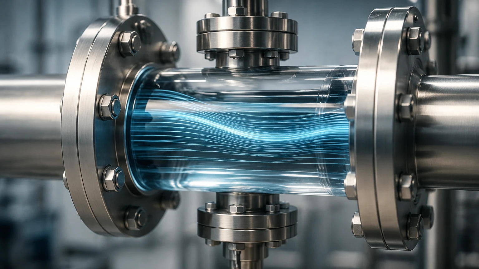
To understand how a laminar flow meter functions, one must first distinguish between laminar and turbulent flow. This distinction is defined by the Reynolds number ($Re$), a dimensionless quantity that represents the ratio of inertial forces to viscous forces. Generally, flow is considered laminar when the Reynolds number is below 2,000. In this state, fluid particles move in smooth, parallel layers (laminae) with minimal lateral mixing.
The Hagen-Poiseuille Law
The fundamental physics governing a laminar flow meter is the Hagen-Poiseuille Law. This principle states that for a Newtonian fluid undergoing laminar flow through a cylindrical pipe of constant cross-section, the pressure drop ($ΔP$) is directly proportional to the volumetric flow rate ($Q$). The relationship is expressed as:
$$Q = \frac{\pi \cdot D^4 \cdot \u0394P}{128 \cdot μ \cdot L}$$
Where:
* $Q$: Volumetric flow rate
* $D$: Diameter of the channel
* $ΔP$: Differential pressure across the element
* $μ$: Dynamic viscosity of the fluid
* $L$: Length of the channel
In a commercial laminar flow meter, the internal geometry is designed to force the fluid into a laminar state using a "laminar flow element" (LFE). Because the diameter ($D$) and length ($L$) are fixed physical constants of the device, the flow rate becomes a linear function of the differential pressure, provided the viscosity remains constant or is accurately compensated for. This linearity is a significant advantage over orifice plates or Venturi meters, where the flow rate is proportional to the square root of the differential pressure, leading to limited rangeability.
Key Components and Construction
A laminar flow meter is more than just a pipe; it is a precision-engineered assembly designed to maintain specific flow conditions. The primary components include:
1. Laminar Flow Element (LFE): This is the core of the device. It typically consists of a matrix of small-diameter capillary tubes, thin parallel plates, or a honeycomb structure. These narrow passages reduce the Reynolds number of the incoming fluid, ensuring it remains laminar even at higher velocities.
2. Differential Pressure (DP) Sensors: These sensors measure the pressure drop across the LFE. High-precision transducers are required to capture the subtle pressure changes associated with low flow rates.
3. Temperature and Pressure Compensation: Since gas viscosity is highly sensitive to temperature changes, and gas density is sensitive to pressure, modern LFMs incorporate integrated temperature and absolute pressure sensors. This data allows the internal electronics to calculate the mass flow rate or standardized volumetric flow rate in real-time.
4. Flow Body: Usually constructed from stainless steel (e.g., 316L) or specialized polymers, the housing must withstand the process pressure and resist corrosion from the measured medium.
Technical Selection Criteria for Industrial Applications
Selecting the right laminar flow meter requires a deep dive into the specific requirements of the process. Engineers must evaluate several critical factors to ensure long-term reliability and accuracy.
Fluid Compatibility and Viscosity
LFMs are most commonly used for clean, dry gases. Because the measurement principle relies heavily on fluid viscosity, the meter must be calibrated for the specific gas mixture in use. If the gas composition changes, the viscosity ($μ$) in the Hagen-Poiseuille equation changes, leading to measurement errors. For liquids, LFMs are less common but can be used for low-viscosity, clean fluids in laboratory or high-precision dosing environments.
Turndown Ratio and Rangeability
One of the primary reasons for choosing a laminar flow meter is its turndown ratio, which often exceeds 100:1. This means a single meter can accurately measure flow from 1% to 100% of its full-scale range. In contrast, many differential pressure meters are limited to a 5:1 or 10:1 ratio. This makes LFMs ideal for processes with high variability in demand.
Accuracy and Repeatability
High-end laminar flow meters offer accuracies in the range of ±0.5% to ±1% of the actual reading. Because the relationship is linear, the accuracy remains consistent across a much wider portion of the flow range compared to non-linear technologies.
Pressure Drop Constraints
While the LFE is necessary to create laminar flow, it also introduces a permanent pressure loss in the system. Engineers must ensure that the available system pressure is sufficient to overcome the resistance of the meter at maximum flow conditions. Typical pressure drops range from 10 mbar to 100 mbar (0.15 to 1.5 PSI) at full scale.
Comparative Analysis: Laminar Flow vs. Alternative Technologies
To assist in the selection process, the following table compares the laminar flow meter with other common flow measurement technologies used in industrial automation.
| Feature | Laminar Flow Meter | Thermal Mass Meter | Orifice Plate (DP) | Ultrasonic Flow Meter |
| :— | :— | :— | :— | :— |
| Primary Fluid | Clean Gases | Gases | Liquids/Gases/Steam | Liquids/Gases |
| Measurement Principle | Viscous Pressure Drop | Heat Transfer | Kinetic Pressure Drop | Transit Time/Doppler |
| Linearity | Excellent (Linear) | Non-linear (Electronic) | Square Root | Linear |
| Turndown Ratio | 100:1 | 50:1 to 100:1 | 5:1 | 50:1 |
| Response Time | Very Fast (<10ms) | Slower (Thermal Lag) | Fast | Moderate |
| Sensitivity to Contamination | High | Moderate | Low | Low |
| Straight Pipe Required | Minimal | Significant | High | Moderate to High |
Installation and Maintenance Best Practices
Proper installation is critical to maintaining the laboratory-grade accuracy of a laminar flow meter in an industrial setting. While LFMs are generally less sensitive to upstream flow profiles than orifice plates, certain precautions must be taken.
Filtration: The Most Critical Factor
The narrow passages within the laminar flow element are susceptible to clogging. Even microscopic particulates can lodge in the capillary tubes, changing the effective diameter ($D$) and length ($L$) of the flow path. This results in an immediate and often undetected shift in calibration. High-efficiency filtration (typically 1 to 5 microns) must be installed upstream of the meter.
Orientation and Piping
Most LFMs can be installed in any orientation, but horizontal installation is often preferred to prevent moisture or condensate from pooling in the element. While the LFE itself conditions the flow, it is still good practice to provide at least 5 diameters of straight pipe upstream and 2 diameters downstream to ensure a stable pressure environment for the DP sensors.
Calibration Cycles
Due to the precision of the LFE, annual calibration is recommended. In applications involving corrosive gases or potential for trace contamination, more frequent verification may be necessary. Many facilities use a master laminar flow meter as a transfer standard to verify other meters on-site.
Integrating Flow and Level Measurement in Process Control
In integrated industrial automation, flow measurement rarely exists in isolation. For instance, in chemical dosing or water treatment plants, the data from a laminar flow meter is often correlated with level measurement data to ensure mass balance and inventory accuracy.
Welk, as a professional manufacturer of industrial level measurement instruments, provides the critical "other half" of this equation. While an LFM monitors the rate of fluid entering a vessel, radar or ultrasonic level sensors monitor the resulting volume. By comparing the integrated flow rate (totalization) with the change in level, engineers can detect leaks, verify pump performance, and ensure that the process remains within safe operating limits. For those looking to optimize their entire measurement loop, it is beneficial to Review product options and application support to find compatible level measurement solutions that complement high-precision flow data.
Common Risks and Troubleshooting
Despite their advantages, laminar flow meters are not "fit and forget" devices. Awareness of common risks can prevent costly downtime.
* Moisture and Condensate: If the gas reaches its dew point within the meter, liquid droplets will block the laminar passages. This creates a massive increase in pressure drop and erroneous flow readings. Heat tracing may be required for high-humidity gas streams.
* Over-pressurization: Subjecting the DP sensor to pressures far beyond its range can damage the diaphragm. Always use bypass valves during system startup and pressure testing.
* Viscosity Shifts: If the gas mixture changes (e.g., a shift in the ratio of Nitrogen to Argon), the meter will remain repeatable but will no longer be accurate. Users must update the viscosity parameters in the flow computer to reflect the new gas composition.
Frequently Asked Questions (FAQ)
Q: Can a laminar flow meter be used for steam?
A: Generally, no. Steam is too close to its phase change point and often contains moisture (wet steam), which would quickly foul the laminar flow element. Orifice plates or vortex meters are better suited for steam applications.
Q: How does a laminar flow meter handle pulsating flow?
A: Because the relationship between flow and pressure is linear, LFMs handle pulsating flow much better than square-root DP meters. However, the electronics must have a sufficiently high sampling rate to capture the peaks and troughs of the pulses.
Q: What is the difference between a laminar flow meter and a laminar flow element?
A: A laminar flow element (LFE) is the physical component that creates the laminar flow. A laminar flow meter is the complete system, including the LFE, the differential pressure sensor, and the flow computer that outputs a readable flow value.
Q: Is straight pipe run required for an LFM?
A: While LFMs are significantly more tolerant of upstream disturbances than other technologies (because the LFE acts as its own flow straightener), providing 5D of straight pipe is still recommended to ensure the highest possible accuracy.
Conclusion
The laminar flow meter is an essential tool for high-precision gas measurement where wide turndown ratios and linear responses are required. By understanding the underlying physics of the Hagen-Poiseuille Law and implementing strict filtration and maintenance protocols, engineers can achieve unparalleled control over their processes. When combined with robust level measurement technologies from providers like Welk, these meters form the backbone of modern, efficient industrial automation systems. For more information on integrating these technologies into your facility, visit the Main Page for technical specifications and engineering support.