Level Control System
Level Control System
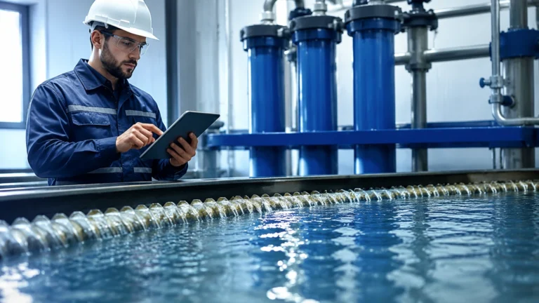
In industrial process automation, a level control system is a fundamental architecture used to monitor and regulate the height of liquids, powders, or granular solids within a vessel. Whether in water treatment plants, chemical processing facilities, or oil and gas refineries, maintaining an accurate level is critical for operational safety, inventory management, and process efficiency. A standard level control system consists of three primary elements: a sensing element (the level meter), a controller (such as a PLC or PID controller), and a final control element (usually a pump or a control valve).
Effective level management prevents hazardous overflows, protects pumps from dry-running, and ensures that chemical reactions occur with the correct volumetric proportions. To design or maintain an effective system, engineers must understand the underlying measurement principles and how they interface with control logic.
Measurement Principles in Level Control
Before selecting components for a level control system, it is essential to understand how different sensing technologies interact with the process media. Welk provides a range of instruments based on various physical principles, each suited to specific environmental conditions.
Radar Level Measurement (Non-contact)
Radar level meters utilize electromagnetic waves, typically in the microwave frequency range (e.g., 26 GHz or 80 GHz). These instruments emit a signal toward the medium's surface, which reflects back to the sensor. By measuring the time-of-flight or the frequency shift (FMCW – Frequency Modulated Continuous Wave), the system calculates the distance to the product.
* Advantages: Radar is unaffected by vacuum, high pressure, or temperature fluctuations. It is highly accurate (often within ±2 mm) and suitable for corrosive or agitated liquids.
* Considerations: The dielectric constant (εr) of the material is crucial; materials with low dielectric constants reflect less energy, requiring more sensitive radar units or stilling wells.
Ultrasonic Level Measurement (Non-contact)
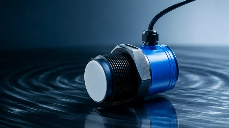
Ultrasonic sensors emit high-frequency sound pulses. The time taken for the echo to return from the liquid surface is used to determine the level. This technology is widely used in water treatment and open-channel flow measurement.
* Advantages: Cost-effective and easy to install as there is no contact with the media.
* Limitations: Sound velocity changes with air temperature, requiring integrated temperature compensation. Furthermore, heavy foam, dust, or steam can absorb or scatter the sound waves, leading to signal loss.
Hydrostatic Level Measurement (Contact)
Hydrostatic transmitters measure the pressure exerted by a liquid column. Based on the formula $P = \rho \cdot g \cdot h$ (where $P$ is pressure, $\rho$ is density, $g$ is gravity, and $h$ is height), the level can be derived if the density of the fluid is constant.
* Advantages: Highly reliable for vented tanks and deep wells. It is a robust technology with no moving parts.
* Limitations: Changes in fluid density (due to temperature or composition changes) will introduce errors unless the system is calibrated for such variations.
Magnetic Level Gauges and Switches
Magnetic level gauges use a float containing a permanent magnet that moves with the liquid level inside a bypass chamber. This magnet flips external rollers for visual indication or triggers reed switches for point level control.
* Advantages: Provides a clear visual reference without requiring power and can be equipped with transmitters for remote monitoring.
* Limitations: Limited to liquids and requires a bypass chamber, which may not be suitable for high-viscosity fluids that could clog the float mechanism.
Components of an Integrated Level Control System
A functional level control system operates as a loop. The integration of hardware and software determines the stability of the process.
1. The Sensor/Transmitter: This is the "eye" of the system. It converts the physical level into an electrical signal, most commonly a 4-20 mA HART signal, or digital protocols like Modbus RS485 or Profibus. For more information on selecting the right sensor for your application, you can visit the Main Page to review product options and application support.
2. The Controller: This device receives the signal from the transmitter. In a simple setup, a digital indicator with relay outputs might suffice. In complex industrial environments, a Programmable Logic Controller (PLC) or a Distributed Control System (DCS) processes the data using PID (Proportional-Integral-Derivative) algorithms to maintain a setpoint.
3. The Final Control Element: Based on the controller's command, a control valve may open or close to regulate inflow/outflow, or a Variable Frequency Drive (VFD) may adjust the speed of a pump to maintain a steady level.
Selection Criteria for Level Control Technology
Choosing the correct technology requires a detailed analysis of the application. The following table provides a comparison of common industrial level measurement technologies used in control systems.
| Technology | Accuracy | Measuring Range | Max Temperature | Key Advantage | Typical Application |
| :— | :— | :— | :— | :— | :— |
| Radar | ±2 mm | Up to 120 m | +450 °C | High precision, non-contact | Chemical reactors, Oil tanks |
| Ultrasonic | ±0.25% | 0.3 – 30 m | +80 °C | Low cost, non-contact | Water sumps, Wastewater |
| Hydrostatic | ±0.1% | 0.5 – 200 m | +100 °C | Simple, submersible | Deep wells, Vented tanks |
| Magnetic | ±5 mm | Up to 6 m | +400 °C | Visual + Electronic | Boilers, Storage tanks |
| Level Switch | N/A | Point Level | +250 °C | High reliability for alarms | Overfill protection |
Key Evaluation Factors
* Media Characteristics: Is the fluid corrosive, viscous, or prone to foaming? Does it have a consistent density?
* Vessel Geometry: Is the tank tall and narrow or short and wide? Are there internal obstructions like agitators or heating coils?
* Process Conditions: What are the maximum operating pressures and temperatures? Is the environment explosive (requiring ATEX/Ex certification)?
* Control Requirements: Is point-level detection (on/off) sufficient, or is continuous measurement required for precise modulation?
Installation Considerations and Best Practices
Proper installation is as critical as selecting the right instrument. Poor placement often leads to "false echoes" or signal instability in a level control system.
* Dead Zones (Blocking Distance): Both ultrasonic and radar sensors have a "dead zone" near the sensor face where measurements are impossible. Sensors must be mounted high enough to ensure the maximum liquid level never enters this zone.
* Nozzle Geometry: For radar and ultrasonic units, the mounting nozzle should be short and wide enough to prevent the signal from reflecting off the nozzle walls. The sensor should typically be positioned at 1/6th of the tank diameter away from the wall to avoid interference.
* Avoiding Obstructions: Sensors should not be mounted directly above inflow pipes, ladders, or agitator blades. If obstructions are unavoidable, many modern radar units offer "false signal suppression" software to mask these reflections.
* Stilling Wells: In tanks with heavy turbulence or foam, installing the sensor inside a stilling well (a vertical pipe) can provide a calm surface for more accurate measurement.
* Venting for Hydrostatic Sensors: Submersible hydrostatic transmitters require a vent tube in the cable to compensate for changes in atmospheric pressure. Ensure this tube is not kinked or blocked by moisture.

Common Risks and Troubleshooting
Even a well-designed level control system can face operational challenges. Engineers should be aware of the following risks:
1. Build-up and Coating: In chemical or wastewater applications, material can build up on the sensor face or float. This can cause "frozen" readings or signal attenuation. Non-contact radar is generally more resistant to this, but extreme build-up may still require periodic cleaning.
2. Vapor and Condensation: Heavy steam or solvent vapors can affect the speed of sound for ultrasonic sensors or cause condensation on the antenna of a radar unit. Using a PTFE-coated antenna or a specialized "purging" port can mitigate these effects.
3. Electrical Interference: Long signal cable runs near high-voltage power lines can introduce EMI (Electromagnetic Interference). Using shielded twisted-pair cables and ensuring proper grounding of the level control system is essential.
4. Density Fluctuations: If a hydrostatic system is calibrated for water (density 1000 kg/m³) but is used for an oil with a density of 800 kg/m³, the level reading will be significantly lower than the actual height. Continuous density compensation may be required if the media changes frequently.
Frequently Asked Questions (FAQ)
Q: Can I use one level control system for multiple tanks?
A: While a single PLC can control multiple tanks, each tank usually requires its own dedicated sensor. Some multi-channel ultrasonic controllers can support up to 10 sensors, reducing the cost per measurement point.
Q: What is the difference between a level transmitter and a level switch?
A: A level transmitter provides continuous measurement (e.g., 0-100% full), allowing for precise control. A level switch provides point-level detection (e.g., "tank is full" or "tank is empty") and is typically used for safety interlocks and alarms.
Q: How often should a level control system be calibrated?
A: Calibration frequency depends on the technology and the criticality of the process. Hydrostatic and magnetic systems may need annual checks, while high-end radar systems are often stable for several years. Regular "bump tests" are recommended for safety-critical systems.
Q: Is radar better than ultrasonic for all applications?
A: Not necessarily. While radar is more versatile, ultrasonic sensors are significantly more cost-effective for simple water and wastewater applications where extreme temperatures and pressures are not present.
Conclusion
A robust level control system is the backbone of safe and efficient industrial fluid management. By understanding the physical principles of radar, ultrasonic, and hydrostatic measurement, and by following rigorous installation standards, engineers can minimize downtime and prevent costly process errors. When designing your system, always confirm the specific chemical compatibility and environmental constraints of your site to ensure long-term instrument reliability.