API 2350 5th Edition Category 3 Response Time
API 2350 5th Edition Category 3 Response Time
In the realm of industrial tank farm management, safety is governed by rigorous standards designed to prevent catastrophic environmental and financial losses. The American Petroleum Institute (API) Standard 2350, specifically the 5th edition, serves as the definitive guide for overfill protection for atmospheric storage tanks. Among its classifications, Category 3 represents the most advanced level of automation. Understanding the api 2350 5th edition category 3 response time is not merely a matter of compliance; it is a critical engineering requirement that dictates the selection, installation, and maintenance of level measurement instrumentation.
The Evolution of Overfill Protection: API 2350 5th Edition
The 5th edition of API 2350 marked a significant shift from prescriptive rules to a risk-based management approach. It emphasizes the implementation of an Overfill Prevention Process (OPP) and integrates the concept of Safety Instrumented Systems (SIS) as defined by IEC 61511.
One of the primary changes in the 5th edition is the refinement of how tanks are categorized based on their level of automation and the human intervention required to prevent an overfill. Category 3 tanks are defined as those equipped with an Automated Overfill Prevention System (AOPS). Unlike Category 1 (manual) or Category 2 (manual with integrated alarms), Category 3 systems must automatically terminate the receipt of product without requiring an operator's action. This automation places a heavy burden on the "response time" of the entire loop, from the sensor to the final control element.
Measurement Principles for Overfill Prevention
Before calculating response times, engineers must understand the measurement principles of the instruments that trigger the AOPS. For Category 3 compliance, the sensor must be independent of the Tank Gauging System (TGS) used for inventory management.
1. Radar Level Measurement (Non-Contact)
Radar level meters, particularly those operating at 80GHz, are the gold standard for Category 3 applications. They emit electromagnetic pulses that reflect off the liquid surface. The time-of-flight is measured to determine the distance.
* Response Speed: Extremely fast, typically providing updates in milliseconds.
* Reliability: High, as there are no moving parts and the signal is unaffected by vapor space conditions.
2. Vibrating Level Switches (Point Level)
Vibrating fork sensors operate on the principle of frequency shift. When the liquid reaches the fork, the vibration frequency changes, triggering an alarm.
* Response Speed: Very fast (usually <1 second).
* Reliability: Excellent for "High-High" (HH) detection as a secondary independent sensor.
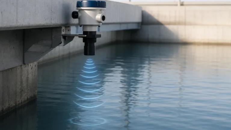
3. Ultrasonic Level Sensors
Similar to radar but using sound waves. These are cost-effective but can be limited by heavy foam or significant temperature gradients in the vapor space.
* Response Speed: Moderate to fast.
* Reliability: Good for non-critical water-based applications, but often secondary to radar in petroleum environments.
4. Hydrostatic Pressure Transmitters
These measure the pressure exerted by the liquid column. While accurate for continuous monitoring, they are dependent on fluid density.
* Response Speed: Slower due to pressure stabilization and electronic damping.
* Reliability: Moderate; they are often used for inventory rather than the primary AOPS sensor.
Defining Category 3 Systems and Requirements
A Category 3 system under API 2350 5th Edition is characterized by its independence and automation. The standard requires that the AOPS be physically and functionally separate from the TGS. This ensures that a failure in the inventory management system does not disable the overfill protection.
The system consists of three main components:
1. The Sensor: Detects the High-High (HH) level.
2. The Logic Solver: A dedicated controller (often a SIL-rated PLC) that processes the sensor signal.
3. The Final Element: An automated valve or pump-stop circuit that halts the flow.
In this configuration, the api 2350 5th edition category 3 response time refers to the total duration from the moment the liquid level passes the HH setpoint to the moment the flow is completely terminated.
Calculating the API 2350 5th Edition Category 3 Response Time
Calculating the required response time is a mathematical exercise that involves the tank's geometry and the maximum possible fill rate. The goal is to ensure the "Response Time" (RT) is shorter than the "Time to Critical High" (TTCH).
The Formula for Total System Response Time
The total response time ($T_{total}$) is the sum of the individual latencies in the loop:
$$T_{total} = T_{sensor} + T_{logic} + T_{valve}$$
* $T_{sensor}$: The time the level meter takes to recognize the level has reached the HH threshold and change its output state.
* $T_{logic}$: The processing time of the PLC and any interposing relays.
* $T_{valve}$: The time required for the actuator to move the valve from fully open to fully closed. This is often the largest component of the total time.
Determining the HH Setpoint
To comply with API 2350, the HH alarm must be positioned at a level that accounts for the maximum volume of liquid that can enter the tank during the $T_{total}$.
1. Identify the Critical High (CH) Level: This is the level where an overfill occurs (e.g., the rim of the tank or the vent inlet).
2. Calculate the Rise Rate: If the maximum inflow is $Q$ ($m^3/s$) and the tank surface area is $A$ ($m^2$), the rise rate is $R = Q/A$ ($m/s$).
3. Calculate the Safety Buffer: $Buffer = R \times T_{total}$.
4. Set the HH Level: $HH = CH – Buffer – Margin$. (The margin accounts for turbulence and sensor accuracy).
For engineers designing these systems, reviewing high-performance instrumentation on the Main Page is essential to ensure that $T_{sensor}$ is minimized, allowing for more flexibility in valve selection and safety margins.
Instrument Selection and Practical Comparison
When selecting instruments for a Category 3 AOPS, the response time of the sensor is a primary variable. Below is a comparison of common technologies used in petroleum and chemical storage.
| Technology | Typical Sensor Response Time | API 2350 Category 3 Suitability | Notes |
| :— | :— | :— | :— |
| 80GHz Radar | < 500 ms | Excellent | High accuracy; unaffected by density or vapor. |
| Guided Wave Radar | 500 ms – 1 s | Very Good | Excellent for low dielectric fluids; immune to turbulence. |
| Vibrating Fork Switch | < 1 s | Excellent | Ideal as an independent HH point-level trigger. |
| Magnetostrictive | 1 s – 2 s | Good | Very accurate but has moving parts (float). |
| Hydrostatic | 2 s – 5 s | Fair | Density changes can affect the perceived HH level. |
| Mechanical Float | 2 s – 10 s | Poor | Prone to sticking; not recommended for AOPS. |
Installation and Maintenance for Compliance
Even the fastest sensor cannot ensure safety if installed incorrectly. For Category 3 systems, the following installation considerations are mandatory:
* Independence: The Category 3 sensor must have its own process connection (nozzle) separate from the TGS. It should not share a stilling well with the inventory gauge unless specifically engineered for redundancy.
* Stilling Wells: If using radar in a tank with internal obstructions or turbulence, a stilling well can improve signal stability, but the holes must be clear to ensure the level inside the well matches the tank level in real-time.
* Testing (Proof Testing): API 2350 5th Edition mandates periodic proof testing. For Category 3, this includes a "full loop test" where the sensor is triggered (either physically or via simulation) to ensure the valve actually closes within the calculated response time.
* Mounting Position: Sensors should be mounted away from the inlet stream to avoid false HH triggers caused by splashing or turbulence, which could lead to unnecessary and costly process shutdowns.
Limitations and Risk Management
While the api 2350 5th edition category 3 response time provides a framework for safety, there are inherent limitations:
1. Valve Latency: In large diameter pipes (e.g., 24 inches or 600mm), a motor-operated valve (MOV) may take 30 to 60 seconds to close. If the tank rise rate is high, the HH level must be set significantly lower, reducing the usable capacity of the tank.
2. Product Properties: High-viscosity liquids can cling to sensors (like vibrating forks), causing a delay in the "reset" of the alarm, though this usually doesn't affect the initial response time for overfill.
3. Communication Latency: If the AOPS uses a digital communication protocol (like WirelessHART or Foundation Fieldbus), the update rate must be configured to meet the response time requirements. Hard-wired 4-20mA or discrete signals are generally preferred for Category 3 for their speed and simplicity.
Frequently Asked Questions
Q: Does API 2350 5th Edition require SIL certification for Category 3?
A: While API 2350 does not strictly mandate a specific Safety Integrity Level (SIL), it heavily references IEC 61511. Most industry best practices involve using SIL 2 rated components for Category 3 AOPS to ensure the probability of failure on demand (PFD) is sufficiently low.
Q: How often should the response time be verified?
A: The response time should be verified during initial commissioning and during every scheduled proof test (typically every 1 to 3 years, depending on the risk assessment of the facility).
Q: Can a single radar meter serve as both the TGS and the Category 3 sensor?
A: No. API 2350 Category 3 requires independence. Using one instrument for both functions creates a single point of failure, which violates the fundamental safety principles of the 5th edition.
Q: What happens if the valve closing time is too slow?
A: If the valve closing time exceeds the safety buffer, the facility must either slow down the maximum fill rate, move the HH setpoint lower, or upgrade to a faster-acting actuator (such as a hydraulic or pneumatic system).
By adhering to the guidelines for api 2350 5th edition category 3 response time, operators can ensure that their automated systems provide a robust defense against overfills. Selecting the right instrumentation is the first step in this process. For comprehensive technical specifications on sensors capable of meeting these stringent requirements, engineers should Review product options and application support to find solutions tailored to their specific process conditions.

Download API 2350 5th Edition Category 3 Response Time as a PDF