Level Control
Level Control
In industrial process automation, level control is the systematic management of the height of liquids, powders, or granular solids within a vessel, tank, or silo. Effective level control is not merely about preventing overflows; it is a critical component of process safety, inventory accuracy, and operational efficiency. From water treatment facilities to complex chemical reactors, the ability to maintain a specific level ensures that pumps do not run dry, vessels are not over-pressurized, and chemical reactions occur within the intended volumetric parameters.
To implement a robust level control system, engineers must understand the interaction between the measurement technology, the physical properties of the media, and the control logic governing the final control elements. This guide examines the principles of level measurement, selection criteria for various industrial environments, and the practical considerations for maintaining precise control loops.
Principles of Level Measurement
Before selecting a control strategy, it is essential to understand how different instruments perceive the level. Welk provides a range of technologies, each operating on distinct physical principles suited to specific industrial challenges.
Radar Level Measurement (Time of Flight)
Radar level meters utilize electromagnetic waves, typically in the 26GHz or 80GHz frequency range. The sensor emits a signal that travels to the surface of the medium, reflects, and returns to the receiver. The instrument calculates the level based on the time of flight (ToF).
* Non-contact Radar: These are ideal for corrosive or hygienic applications as the sensor does not touch the media. Modern 80GHz radar units offer a narrow beam angle, which minimizes interference from internal tank structures like agitators or heating coils.
* Guided Wave Radar (GWR): This utilizes a probe to guide the electromagnetic pulse. GWR is particularly effective in applications with low dielectric constants or where heavy foam and turbulence are present, as the probe focuses the signal energy.
Ultrasonic Level Measurement
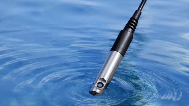
Ultrasonic sensors function similarly to radar but use acoustic waves (sound) instead of electromagnetic waves. The transducer emits an ultrasonic pulse that reflects off the surface of the liquid. The time taken for the echo to return is proportional to the distance. Because the speed of sound is affected by air temperature, Welk ultrasonic sensors include integrated temperature compensation to maintain accuracy across varying environmental conditions. These are cost-effective solutions for water and wastewater applications but are limited in vacuum or high-pressure environments where sound cannot propagate effectively.
Hydrostatic Level Measurement
Hydrostatic transmitters measure the pressure exerted by a liquid column at a specific point. The relationship is defined by the formula: $P = \rho \cdot g \cdot h$, where $P$ is pressure, $\rho$ is the density of the liquid, $g$ is gravity, and $h$ is the height of the liquid. By measuring the pressure at the bottom of a tank, the level can be calculated if the density remains constant. This technology is highly reliable for vented tanks and deep wells, provided the media density is well-defined.
Magnetic Level Gauges
Magnetic level gauges rely on buoyancy and magnetic coupling. A float containing a permanent magnet moves with the liquid level inside a bypass chamber. Outside the chamber, a series of magnetic flags or a transmitter responds to the float's position. This provides both a clear visual indication and a continuous electrical signal for level control, making it a favorite for high-temperature and high-pressure boiler applications.
Point Level Detection (Switches)
Level switches do not provide a continuous measurement but rather a binary signal (On/Off) when the media reaches a specific height. Technologies include vibrating forks, which detect changes in resonance frequency when submerged, and float switches, which use mechanical or reed-switch activation. These are critical for "High-High" and "Low-Low" alarm states in a level control loop.
Designing a Level Control Strategy
Level control typically follows one of two primary architectures: Point Level Control or Continuous Level Control.
Point Level Control (On/Off)
In simpler systems, level control is achieved using two or more switches. For example, in a sump pump application, a "High" switch triggers the pump to start, and a "Low" switch stops it once the vessel is drained. This is known as hysteresis or "deadband" control. It prevents the pump from rapidly cycling (chattering), which would lead to premature motor failure.
Continuous Level Control (PID Loops)
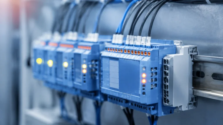
For processes requiring a steady state—such as a boiler feed-water system—continuous level control is necessary. A transmitter (Radar, Ultrasonic, or Hydrostatic) sends a 4-20mA or digital signal (HART, Modbus) to a Programmable Logic Controller (PLC) or Distributed Control System (DCS).
The controller compares the "Process Variable" (current level) to the "Set Point" (desired level) and adjusts a "Final Control Element," such as a modulating valve or a Variable Frequency Drive (VFD) on a pump. Proportional-Integral-Derivative (PID) logic is usually employed to ensure the level returns to the set point quickly without excessive oscillation.
Selection Criteria for Level Control Instrumentation
Choosing the right instrument requires an analysis of the process environment. No single technology is universal. The following table provides a general comparison for common industrial scenarios:
| Technology | Media Type | Accuracy | Max Range | Key Advantage |
| :— | :— | :— | :— | :— |
| 80GHz Radar | Liquids/Solids | ±1 mm | 120 m | High precision, ignores internal obstructions |
| Ultrasonic | Liquids/Slurries | ±0.25% | 30 m | Non-contact, cost-effective for water |
| Hydrostatic | Clean Liquids | ±0.1% | 200 m | Simple installation, ideal for deep wells |
| Magnetic Gauge | Hazardous Liquids | ±5 mm | 6 m | Visual indication + high safety rating |
| Vibrating Fork | Most Media | N/A (Point) | N/A | Reliable overfill protection, maintenance-free |
Critical Evaluation Factors:
1. Media Properties: Is the liquid corrosive, viscous, or prone to coating? Radar is often preferred for corrosive media, while hydrostatic sensors require specialized diaphragm materials like Tantalum or Hastelloy.
2. Vessel Geometry: Small tanks with narrow diameters benefit from the focused beam of 80GHz radar. Tall, narrow silos may require guided wave radar to avoid signal loss.
3. Process Conditions: High pressures (above 40 bar) and temperatures (above 150°C) generally exclude standard ultrasonic sensors, making radar or magnetic gauges more appropriate.
4. Vapor and Foam: Heavy steam or surface foam can absorb ultrasonic signals. In these cases, radar—specifically guided wave radar—is the superior choice for level control.
Installation and Engineering Best Practices
Even the most advanced level control instrument will fail if installed incorrectly. Engineering teams should adhere to the following guidelines to ensure signal integrity:
* Avoid the Inflow Stream: Never install a level sensor directly above the pipe where the tank is filled. The turbulence and falling liquid will create false readings and signal noise.
* The "Dead Zone" or Blocking Distance: All non-contact sensors (Radar and Ultrasonic) have a minimum distance near the transducer where they cannot measure. Ensure the maximum possible liquid level does not enter this zone.
* Nozzle Geometry: For radar and ultrasonic units, the mounting nozzle should be as short as possible. If a nozzle is too long or narrow, the signal may reflect off the nozzle walls rather than the liquid surface.
* Stilling Wells: In tanks with heavy agitation or surface vortexes, installing the sensor inside a stilling well (a perforated pipe) can provide a calm surface for more accurate measurement.
* Hydrostatic Venting: Submersible hydrostatic transmitters must have a vent tube in their cable to compensate for changes in atmospheric pressure. Ensure this tube is not kinked and is protected by a moisture-wicking filter.
Common Risks and Limitations in Level Control
Understanding the failure modes of level control systems is essential for risk mitigation.
1. Dielectric Constant ($ε_r$): Radar relies on the reflectivity of the media. Materials with very low dielectric constants (like certain oils or liquefied gases) reflect very little energy. If $ε_r < 1.4$, specialized high-sensitivity radar or guided wave radar with a coaxial probe is required.
2. Density Fluctuations: Hydrostatic level control assumes a constant density. If a process involves mixing different chemicals or significant temperature swings that change the liquid's density, the level reading will drift. In such cases, a non-contact method is preferred.
3. Build-up and Coating: In applications like wastewater or lime slurry, material can build up on the sensor face. While some Welk radar units feature "mapping" software to ignore static build-up, heavy coating will eventually attenuate the signal, requiring periodic maintenance or the use of a self-cleaning vibrating fork.
4. Turbulence and Agitation: Rapidly moving surfaces can scatter ultrasonic and radar signals. While software filtering can smooth out these fluctuations, the mechanical solution—such as a stilling well—is often the most robust fix for level control stability.
Frequently Asked Questions (FAQ)
Q: How often should level control sensors be calibrated?
A: This depends on the technology and the criticality of the process. Hydrostatic sensors may drift over time and should be checked annually. Radar and ultrasonic sensors are generally more stable, but their loop output (4-20mA) should be verified every 12 to 24 months to ensure the PLC is receiving the correct data.
Q: Can one sensor be used for both control and safety?
A: In high-risk environments (SIL rated), it is standard practice to separate the control sensor from the safety sensor. For example, a radar unit might handle the daily level control, while a completely independent vibrating fork switch acts as the high-level emergency shutdown (ESD).
Q: What is the impact of tank pressure on ultrasonic sensors?
A: Ultrasonic sensors rely on air as a medium. As pressure increases, the density of the air changes, which alters the speed of sound. Furthermore, at high pressures, the transducer's ability to vibrate is dampened. Generally, ultrasonic sensors should not be used in applications exceeding 3 bar of pressure.
Q: How do I choose between 26GHz and 80GHz radar?
A: 80GHz radar is superior for most applications due to its smaller antenna size and narrower beam (approx. 3° vs 10° for 26GHz). However, 26GHz radar can be more effective in environments with extremely heavy dust or very thick steam, as the longer wavelength can penetrate these particles more easily.
Conclusion
Effective level control is a synergy of physics, mechanical engineering, and electronics. By matching the measurement principle to the specific constraints of the media and the vessel, operators can achieve high levels of precision and safety. Whether you are managing simple water storage or complex chemical processing, selecting a high-quality instrument is the first step toward a reliable control loop. For detailed technical specifications and to explore the full range of instrumentation, visit the Main Page of Welk's product catalog for comprehensive application support and product options.