Level Controller
Level Controller
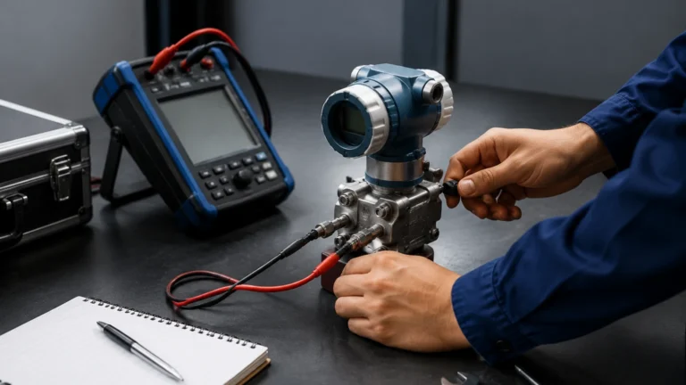
In industrial automation, a level controller is a critical component used to manage the volume of liquids or solids within a vessel, tank, or silo. While level measurement instruments—such as radar meters or ultrasonic sensors—provide the data regarding the current state of the medium, the level controller acts as the processing unit that interprets this data and executes a command. This command typically involves activating a pump, opening a valve, or triggering an alarm to maintain a specific setpoint or prevent hazardous conditions like overflows and dry runs.
Effective level control is fundamental to process safety, inventory management, and operational efficiency across industries ranging from water treatment and chemical processing to oil and gas. Selecting the correct level controller requires a deep understanding of the underlying measurement principles, the physical properties of the medium, and the specific requirements of the control logic.
Measurement Principles and Input Sources
Before a level controller can perform its function, it must receive an accurate signal from a primary sensing element. The choice of sensor determines the reliability of the control loop. Welk provides a variety of technologies that serve as the input for modern level control systems.
Radar Level Measurement
Radar level meters utilize the Time-of-Flight (ToF) principle. The device emits high-frequency microwave pulses (typically in the 26 GHz or 80 GHz range) that travel to the surface of the medium and reflect back to the sensor. The time taken for the signal to return is proportional to the distance. Radar is highly valued for level control because it is non-contact and largely unaffected by changes in temperature, pressure, or the presence of vapors.
Ultrasonic Level Sensing
Similar to radar, ultrasonic sensors use ToF but rely on sound waves rather than electromagnetic waves. These are cost-effective solutions for water and wastewater applications. However, they are sensitive to air temperature fluctuations (which affect the speed of sound) and can be hindered by heavy foam or vacuum conditions.
Hydrostatic Pressure
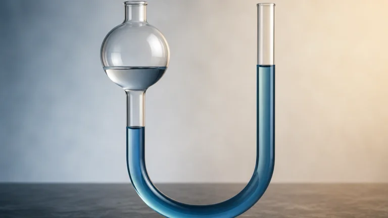
Hydrostatic level transmitters measure the pressure exerted by a liquid column at the bottom of a tank. Based on the formula $P = \rho gh$ (where $P$ is pressure, $\rho$ is density, $g$ is gravity, and $h$ is height), the controller can calculate the level if the density of the liquid remains constant. This is a common method for vented tanks and deep wells.
Magnetic and Float-Based Systems
Magnetic level gauges and float switches provide mechanical or electromechanical feedback. A float moves with the liquid level, and its position is transmitted via a magnetic coupling to a switch or a continuous transmitter. These are often used for direct visual indication and redundant high-level alarms.
Types of Level Control Logic
Level controllers are generally categorized by the type of control action they perform: discrete (On/Off) or continuous.
1. Point Level Control (On/Off)
Point level control is the simplest form of automation. It utilizes level switches installed at specific heights (e.g., high-level and low-level). When the medium reaches the switch, the controller receives a binary signal (open/closed) and reacts accordingly.
* High-Level Cutoff: Prevents tank overfill by closing an inlet valve or stopping a feed pump.
* Low-Level Protection: Protects pumps from cavitation or dry running by shutting them down when the level drops below a safe threshold.
2. Continuous Level Control
Continuous control involves maintaining the level at a specific setpoint or within a narrow range using a modulating output. The controller receives a continuous signal (typically 4-20mA, 0-10V, or a digital protocol like HART or RS485) and uses a control algorithm, such as Proportional-Integral-Derivative (PID), to adjust the process.
* Inflow Control: The controller adjusts an inlet valve to match the outflow, keeping the level steady.
* Outflow Control: Common in buffer tanks where the level is allowed to fluctuate within limits to ensure a steady feed to downstream equipment.
Technical Selection Criteria
Choosing the right level controller and associated sensor requires evaluating several technical parameters. The following table provides a comparison of common technologies used in level control loops:
| Technology | Accuracy | Medium Type | Best For | Limitations |
| :— | :— | :— | :— | :— |
| Radar | ±1 mm to ±5 mm | Liquids/Solids | Corrosive chemicals, high temp | High initial cost |
| Ultrasonic | ±0.25% of range | Liquids | Water treatment, open channels | Affected by foam and dust |
| Hydrostatic | ±0.1% to ±0.5% | Liquids | Deep tanks, constant density | Sensitive to density changes |
| Magnetic | ±5 mm to ±10 mm | Liquids | High pressure, visual monitoring | Moving parts subject to wear |
| Capacitance | ±1% | Liquids/Solids | Small tanks, interface level | Requires dielectric stability |
Process Conditions
* Temperature and Pressure: High-pressure reactors require robust seals and non-contact methods like radar. Hydrostatic sensors must be rated for the maximum process pressure.
* Chemical Compatibility: Wetted parts (probes, diaphragms, floats) must be resistant to the medium. Stainless steel 316L, PTFE, and Hastelloy are common materials for aggressive chemicals.
* Dielectric Constant ($ε_r$): For radar and capacitance sensors, the dielectric constant of the medium dictates signal strength. Low $ε_r$ materials (like oils) reflect less energy than high $ε_r$ materials (like water).
Installation and Engineering Considerations
Proper installation is paramount to ensuring the level controller receives accurate data. Engineers should consult the Main Page for specific product dimensions and mounting requirements.
1. Avoid Obstructions: For radar and ultrasonic sensors, the signal beam must be clear of internal tank structures like ladders, agitators, or heating coils. If obstructions are unavoidable, many modern controllers offer "false echo suppression" to ignore these fixed reflections.
2. Nozzle Height and Diameter: The mounting nozzle should be as short as possible to prevent signal interference at the top of the tank (the "near-zone" or "dead zone").
3. Inflow Streams: Sensors should never be mounted directly above the point where the medium enters the tank. Turbulence and splashing can cause erratic readings and premature wear on mechanical components.
4. Stilling Wells: In tanks with heavy agitation or surface turbulence, a stilling well (a vertical pipe) can be used to provide a calm surface for the sensor to measure.
5. Grounding and Shielding: To prevent electrical noise from interfering with the 4-20mA signal, shielded cables should be used, and the instrument must be properly grounded according to local industrial standards.

Common Risks and Limitations
While modern level controllers are highly advanced, certain environmental factors can introduce risks to accuracy:
* Vapor and Condensation: In closed tanks, condensation can form on the sensor face. Some ultrasonic sensors struggle with this, whereas radar with a drip-off antenna design is less affected.
* Foam: Heavy, thick foam can absorb ultrasonic and radar signals, leading to a "loss of echo." In these cases, hydrostatic or displacer-type controllers may be more reliable.
* Build-up: Sticky or viscous media can coat probes or floats. Non-contact radar is the preferred solution for coating media, as it does not rely on physical contact with the substance.
* Ambient Noise: High-frequency acoustic noise in a factory can occasionally interfere with ultrasonic sensors, though digital filtering in the level controller can mitigate this.
Frequently Asked Questions (FAQ)
Q: Can a single level controller manage multiple tanks?
A: Yes, many multi-channel digital controllers can accept inputs from several sensors and manage multiple control outputs, though this increases the complexity of the wiring and programming.
Q: What is the difference between a level transmitter and a level controller?
A: A transmitter measures the level and sends a signal (e.g., 4-20mA). A controller receives that signal, compares it to a setpoint, and decides what action to take (e.g., turning on a pump).
Q: How do I handle level control in a tank with a vacuum?
A: Ultrasonic sensors generally fail in a vacuum because sound requires a medium to travel. Radar or hydrostatic pressure (using a differential pressure transmitter to compensate for the vacuum) are the standard choices.
Q: What is a "dead zone" in level measurement?
A: The dead zone (or blocking distance) is the area directly below the sensor where it cannot accurately measure. For example, if an ultrasonic sensor has a 0.3-meter dead zone, the tank cannot be controlled accurately once the liquid is within 0.3 meters of the sensor face.
Conclusion for Project Implementation
Implementing a robust level control system requires more than just purchasing a sensor; it requires an integrated approach to sensing, logic, and actuation. Before finalizing a project specification, engineers should confirm the maximum and minimum process temperatures, the chemical nature of the medium, and the required precision of the control loop.
For specialized applications, such as those involving explosive atmospheres (ATEX/IECEx requirements) or highly corrosive acids, customized OEM/ODM solutions may be necessary to ensure long-term reliability. By selecting the appropriate measurement principle and configuring the level controller with the correct hysteresis and damping settings, industrial operators can achieve stable, safe, and automated process environments.