Level Sensor for Oil Tank
Level Sensor for Oil Tank
In industrial environments, the selection of a level sensor for oil tank applications is a critical engineering decision that impacts operational safety, inventory accuracy, and environmental compliance. Whether managing crude oil in large-scale storage terminals, fuel in standby generator tanks, or lubricants in manufacturing facilities, the physical properties of the oil—such as viscosity, dielectric constant, and vapor pressure—dictate the appropriate measurement technology.
This guide examines the primary measurement principles used in modern oil level monitoring, provides selection criteria for various tank configurations, and outlines the technical considerations necessary for reliable long-term performance. For a comprehensive overview of available industrial instrumentation, professionals can consult the Main Page of our technical catalog to review specific product specifications.
Measurement Principles for Oil Level Sensing
Selecting the correct level sensor for oil tank monitoring requires an understanding of how different technologies interact with the fluid and the headspace of the tank. Oil presents unique challenges, including the potential for vapor accumulation, varying densities due to temperature fluctuations, and low dielectric constants.
Radar Level Measurement (Non-Contact and Guided Wave)
Radar technology is widely considered the gold standard for oil level measurement due to its high accuracy and independence from the physical properties of the medium (density and pressure).
* Non-Contact Radar: These sensors emit high-frequency electromagnetic pulses (typically in the 26 GHz or 80 GHz range). The pulses reflect off the oil surface and return to the sensor. The time-of-flight is used to calculate the distance. 80 GHz radar is particularly effective for oil because its narrow beam angle avoids internal tank obstructions like heating coils or agitators.
* Guided Wave Radar (GWR): GWR uses a probe (cable or rod) to guide the microwave pulse to the liquid surface. This is highly effective for oils with low dielectric constants ($ε_r$), as the probe concentrates the energy, ensuring a stronger return signal even from poorly reflective surfaces.
Ultrasonic Level Measurement
Ultrasonic sensors function by emitting sound waves that bounce off the liquid surface. While cost-effective, they are generally reserved for non-volatile oils. In many oil tank applications, the presence of heavy vapors or significant temperature gradients in the headspace can alter the speed of sound, leading to measurement errors. Furthermore, if the oil surface produces foam, the ultrasonic signal may be absorbed rather than reflected.
Hydrostatic Pressure Measurement
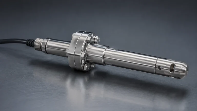
Hydrostatic sensors measure the pressure exerted by the liquid column above the sensor diaphragm. Since pressure is directly proportional to the height of the liquid and its density ($P = ρgh$), these sensors are reliable and simple to install. However, because oil density changes with temperature, hydrostatic systems often require temperature compensation to maintain accuracy in outdoor storage tanks.
Magnetic Level Gauges
Magnetic gauges utilize a float containing a permanent magnet that moves with the liquid level inside a bypass chamber. This motion is coupled with an external indicator or a reed-chain transmitter. This technology provides both a local visual reading and a remote electronic signal, making it ideal for high-pressure or high-temperature oil applications where power may be intermittent.
Technical Selection Criteria
When specifying a level sensor for oil tank installations, engineers must evaluate several variables to ensure the chosen instrument matches the application's demands.
Media Properties
* Dielectric Constant (ε_r): Most oils have a low dielectric constant (typically 1.8 to 2.5). This is a critical factor for radar sensors. Non-contact radar may require high-sensitivity electronics or a stilling well to boost the signal-to-noise ratio, while GWR is inherently better suited for low ε_r fluids.
* Viscosity: Highly viscous oils, such as heavy fuel oil (HFO) or crude, can cause build-up on probes or floats. In these cases, non-contact radar or flush-diaphragm hydrostatic transmitters are preferred to minimize maintenance.
* Temperature and Pressure: Storage tanks for heavy oils often require heating to maintain flow. Sensors must be rated for the operating temperature and the potential for thermal expansion of the tank shell.
Tank Geometry and Environment
* Tank Shape: Tall, narrow tanks benefit from the narrow beam of 80 GHz radar. Horizontal cylindrical tanks require sensors with software that can calculate volume based on the non-linear relationship between height and capacity.
* Internal Obstructions: Manways, ladders, and heating coils can create "false echoes" for radar and ultrasonic sensors. Modern sensors include "false signal suppression" to map out these reflections.
* Hazardous Areas: Most oil storage environments are classified as hazardous (Class I, Div 1/2 or ATEX Zone 0/1). Sensors must carry the appropriate explosion-proof or intrinsically safe certifications.
Practical Selection Table
The following table provides a comparison of common technologies used for oil level measurement:
| Technology | Accuracy | Ideal Oil Type | Advantages | Limitations |
| :— | :— | :— | :— | :— |
| 80 GHz Radar | ±1 mm | All oils (Crude, Diesel, Lube) | Non-contact, high precision, ignores vapors. | Higher initial cost. |
| Guided Wave Radar | ±2 mm | Low dielectric oils, small tanks | Reliable in foam/turbulence. | Probe contact; build-up risk. |
| Ultrasonic | ±0.25% | Lubricants, non-volatile oils | Low cost, easy setup. | Sensitive to vapor and foam. |
| Hydrostatic | ±0.1% to 0.5% | Diesel, hydraulic oil | Simple, robust, submersed options. | Requires density compensation. |
| Magnetic Gauge | ±5 mm | High-temp/High-pressure oil | Visual + Electronic; no power for visual. | Moving parts; bypass piping needed. |
Installation Considerations
Proper installation is as important as technology selection. Even the most advanced level sensor for oil tank applications will fail if installed incorrectly.
1. Nozzle Placement: For non-contact sensors, the nozzle should be located away from the tank wall to avoid interference (typically at least 200 mm or 8 inches from the wall). It should also be positioned away from the fill inlet to avoid measuring the turbulence of incoming oil.
2. Stilling Wells and Bypass Pipes: If the oil surface is turbulent or has a very low dielectric constant, installing the sensor inside a stilling well (a vertical pipe) can stabilize the surface and amplify the radar signal.
3. Dead Zones (Blocking Distance): Every sensor has a "dead zone" near the top where it cannot measure. Ensure the sensor is mounted high enough that the maximum oil level never enters this zone.
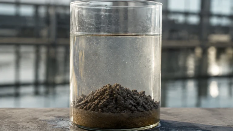
4. Orientation: Hydrostatic sensors should be mounted where they will not be buried by sediment or sludge that often settles at the bottom of oil tanks. Using a side-mounted flange or a suspended cable-type transmitter can mitigate this risk.

Limitations and Common Risks
Engineers should be aware of specific risks that can compromise measurement integrity in oil applications:
* Vapor and Condensation: While radar is mostly unaffected, heavy condensation on the sensor face can attenuate the signal. Sensors with PTFE or PEEK encapsulated antennas are recommended for their self-cleaning properties.
* Paraffin and Wax Build-up: Crude oil often contains paraffin that can solidify on probes or floats. In these environments, non-contact measurement is almost always the superior choice to prevent mechanical failure.
* Density Variation: For hydrostatic sensors, a change in oil temperature from 10°C to 40°C can result in a significant density shift. If the PLC/controller is not programmed to compensate for this, the calculated level will be inaccurate.
* Tank Grounding: For radar and GWR, the tank must be properly grounded to ensure electromagnetic compatibility and safety in explosive atmospheres.
Frequently Asked Questions (FAQ)
Q: Can I use an ultrasonic sensor for a diesel storage tank?
A: It is possible, but not recommended if the tank is outdoors or subject to temperature swings. Diesel vapors can change the air density in the tank, causing the ultrasonic sensor to report inaccurate levels. Radar is a more reliable choice for diesel.
Q: How do I measure the interface between oil and water?
A: Guided Wave Radar (GWR) is the most effective technology for interface measurement. The microwave pulse passes through the upper oil layer (low dielectric) and reflects off the water layer (high dielectric), allowing the sensor to track both the total level and the interface level simultaneously.
Q: What is the maintenance requirement for a radar level sensor?
A: Non-contact radar sensors are virtually maintenance-free because they have no moving parts and do not touch the oil. Periodic verification of the electronics and cleaning of the antenna (if heavy build-up occurs) are the only standard requirements.
Q: Does the tank material affect the sensor choice?
A: Yes. For example, radar sensors require a metal tank or a metal mounting flange to provide a proper reference ground. If using a plastic or fiberglass tank, special mounting considerations or GWR may be required.
Conclusion
Selecting a level sensor for oil tank applications requires a balanced evaluation of accuracy requirements, fluid characteristics, and environmental constraints. While hydrostatic and magnetic sensors offer robust performance for specific scenarios, radar technology—particularly 80 GHz non-contact radar—has become the industry standard for its versatility and precision across the widest range of oil types.
By following the measurement principles and installation guidelines outlined above, facility managers and engineers can ensure reliable inventory data and enhanced safety. For detailed product selection and application engineering support, visit our Main Page to connect with our technical team.