Level Sensor for Tanks
Level Sensor for Tanks
In industrial process control, the selection of a level sensor for tanks is a critical decision that impacts safety, efficiency, and inventory management. Whether managing water treatment facilities, chemical processing plants, or oil and gas storage, accurate level measurement ensures that tanks do not overflow, pumps do not run dry, and production remains continuous. Modern industrial environments require a variety of technologies to handle diverse media, ranging from corrosive acids to viscous hydrocarbons and dry bulk solids.
Welk, a professional manufacturer of industrial level measurement instruments, provides a comprehensive suite of solutions including radar, ultrasonic, hydrostatic, and magnetic technologies. Understanding the underlying physical principles of these sensors is the first step in selecting the correct instrument for a specific tank application. For a complete overview of available technologies, engineers can refer to the Main Page for detailed product specifications.
Measurement Principles of Common Tank Level Sensors
Before selecting a level sensor for tanks, it is essential to understand how different technologies interact with the stored media and the tank environment.
Radar Level Measurement (ToF)
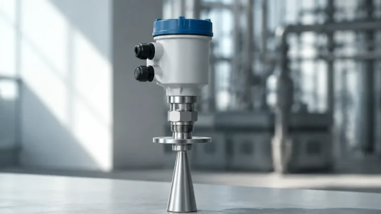
Radar level sensors operate on the Time-of-Flight (ToF) principle. The sensor emits high-frequency electromagnetic waves (typically in the 26GHz or 80GHz range) toward the product surface. These waves are reflected back to the sensor. The time taken for the signal to travel to the surface and back is directly proportional to the distance.
* Non-Contact Radar: Ideal for corrosive or hygienic applications where the sensor should not touch the media. 80GHz radar is particularly effective due to its narrow beam angle, which avoids internal tank obstructions like agitators.
* Guided Wave Radar (GWR): Uses a probe (cable or rod) to guide the microwave signal. This is highly effective for low dielectric constants or when heavy foam is present on the liquid surface.
Ultrasonic Level Measurement
Ultrasonic sensors use sound waves rather than electromagnetic waves. The transducer emits an ultrasonic pulse that reflects off the liquid surface. By measuring the time interval between emission and reception, the device calculates the distance. Since sound speed is affected by air temperature, these sensors usually include integrated temperature compensation. They are cost-effective for standard water and wastewater applications but may struggle in vacuum conditions or where heavy steam is present.
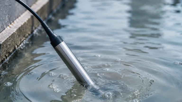
Hydrostatic Pressure Measurement
This method relies on the principle that the pressure at a specific depth in a liquid is proportional to the height of the liquid column above it (P = ρgh). A pressure transmitter mounted at the bottom of the tank (or submerged) measures the head pressure. This technology is robust and widely used in deep reservoirs and vented tanks. However, it requires an accurate knowledge of the liquid's density to provide precise level readings.
Magnetic Level Gauges
Magnetic level gauges utilize a float containing a permanent magnet that moves with the liquid level in a bypass chamber. This magnet actuates a series of external flags or a transmitter. This provides a clear visual indication without requiring power, making it a preferred choice for high-pressure boilers and hazardous chemical storage where visual redundancy is required.
Practical Selection Criteria for Tank Applications
Selecting the right level sensor for tanks involves evaluating the physical properties of the media, the geometry of the vessel, and the environmental conditions. Engineers should use the following criteria as a framework for evaluation.
Media Properties
* Dielectric Constant (εr): For radar sensors, the reflectivity of the surface depends on the dielectric constant. Materials with low εr (like oils) reflect less energy than those with high εr (like water).
* Viscosity and Coating: Highly viscous liquids can coat probes in guided wave radar or float-based systems, leading to measurement errors. Non-contact radar or ultrasonic sensors are often preferred here.
* Corrosiveness: For aggressive chemicals, sensors must be constructed from compatible materials such as PTFE, PVDF, or high-grade stainless steel (316L).
Tank Geometry and Obstructions
* Internal Obstacles: Agitators, heating coils, and ladders can create false echoes. Sensors with narrow beam angles (like 80GHz radar) or advanced software that filters out static echoes are necessary in these environments.
* Tank Shape: Spherical or horizontal cylindrical tanks require volume linearization in the transmitter's software to convert level height into accurate volume units (liters or cubic meters).
Environmental Conditions
* Temperature and Pressure: Extreme temperatures (above 200°C / 392°F) or high pressures (above 40 bar / 580 psi) typically necessitate specialized radar or magnetic level gauges.
* Vapor and Dust: Heavy dust in silos or thick steam in process tanks can attenuate ultrasonic signals. Radar is generally more resistant to these conditions.
Technology Comparison Table
| Technology | Typical Accuracy | Max Range | Media Type | Key Advantage |
| :— | :— | :— | :— | :— |
| 80GHz Radar | ±1 mm (0.04 in) | 120 m (394 ft) | Liquids & Solids | High precision; narrow beam |
| Ultrasonic | ±0.25% of range | 15 m (49 ft) | Liquids | Cost-effective; non-contact |
| Hydrostatic | ±0.1% to 0.5% | 200 m (656 ft) | Liquids | Simple; ideal for deep tanks |
| Guided Wave Radar | ±2 mm (0.08 in) | 30 m (98 ft) | Liquids & Powders | Works in foam and low εr |
| Magnetic Gauge | ±5 mm (0.2 in) | 6 m (20 ft) | Liquids | Visual indication; no power |
Installation Considerations and Best Practices
Correct installation is as important as technology selection. Improperly mounted sensors are the leading cause of measurement instability.
1. Nozzle Dimensions: For radar and ultrasonic sensors, the nozzle height and diameter must be considered. If the nozzle is too narrow or too long, the signal may reflect off the nozzle walls before reaching the media.
2. Dead Zones (Blocking Distance): Every non-contact sensor has a "dead zone" directly beneath the transducer where measurements cannot be taken. Ensure the sensor is mounted high enough so the maximum liquid level does not enter this zone.
3. Positioning: Sensors should never be mounted in the center of a tank (to avoid the focal point of echoes in domed tanks) or too close to the wall (to avoid side-wall interference). A position approximately 1/4 to 1/3 of the tank diameter from the wall is usually ideal.
4. Avoid the Filling Stream: Do not install the level sensor for tanks directly above the inlet pipe. The turbulence and falling liquid will cause erratic readings and signal noise.
5. Venting: For hydrostatic sensors in atmospheric tanks, the reference side of the pressure sensor must be vented to the atmosphere to compensate for changes in barometric pressure.
Limitations and Operational Risks
While modern sensors are highly advanced, they are not without limitations. Recognizing these risks prevents operational failures.
* Foam Interference: Thick, dense foam can absorb ultrasonic and radar signals. In such cases, Guided Wave Radar or Hydrostatic transmitters are more reliable as they measure through or beneath the foam.
* Turbulence: Rapidly mixing liquids can cause a "choppy" surface, scattering the signal. Software damping or the use of a stilling well (a pipe that stabilizes the liquid surface) can mitigate this.
* Vacuum Conditions: Ultrasonic sensors cannot function in a vacuum because sound waves require a medium (air/gas) to travel. Radar is the only non-contact option for vacuum tanks.
* Build-up: In solids measurement or with sticky liquids, material build-up on the sensor face can attenuate the signal. Many Welk radar sensors feature a "lens" antenna design that minimizes the impact of condensation and build-up.
Frequently Asked Questions (FAQs)
Q: How do I calibrate a level sensor for a non-linear tank?
A: Most modern transmitters allow you to input a "strapping table" or select a tank shape (e.g., horizontal cylinder) in the configuration menu. This automatically converts the measured height into a volume reading.
Q: Can one sensor be used for both liquids and solids?
A: Radar sensors are versatile enough for both, but the antenna design and software algorithms differ. Solids require a sensor capable of handling uneven surfaces and lower reflectivity.
Q: What maintenance is required for a level sensor for tanks?
A: Non-contact sensors are virtually maintenance-free. However, for contact-based systems like magnetic gauges or hydrostatic probes, periodic inspection for scaling, corrosion, or debris build-up is recommended to ensure the float or diaphragm moves freely.
Q: How does temperature affect measurement?
A: In ultrasonic sensors, temperature significantly changes the speed of sound, requiring active compensation. In hydrostatic sensors, temperature changes affect liquid density, which can introduce errors if not accounted for. Radar is largely unaffected by temperature variations in the vapor space.
For industrial operators seeking a reliable level sensor for tanks, the choice depends on balancing technical requirements with budget constraints. By following the principles of measurement and adhering to strict installation guidelines, facilities can achieve high-precision monitoring. For further assistance with technical selection or to view our full product catalog, please visit our Main Page.