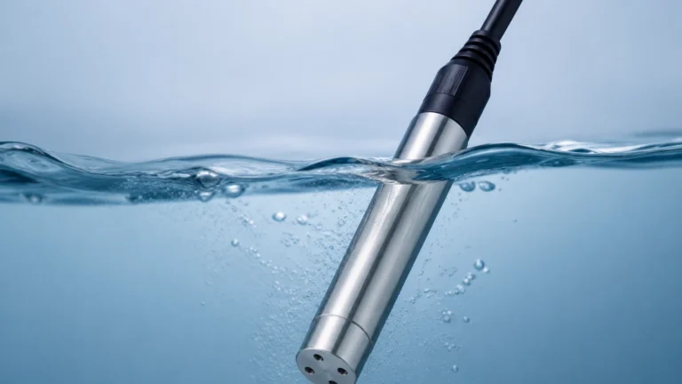
Turbudity Sensor
Turbudity Sensor
In industrial process control and environmental monitoring, the measurement of liquid clarity is a fundamental parameter for ensuring product quality and regulatory compliance. A turbudity sensor (commonly referred to in technical literature as a turbidity sensor) is an optoelectronic device designed to quantify the concentration of suspended solids within a liquid medium. By measuring how light interacts with particles in a fluid, these sensors provide real-time data essential for water treatment, chemical processing, and food production.
Understanding the nuances of optical measurement is critical for engineers and plant managers. This guide examines the principles of turbidity measurement, the selection criteria for industrial applications, and the practical considerations for integrating these sensors into existing automation frameworks. For a broader look at industrial instrumentation and level control, you may review product options and application support on our Main Page.
Measurement Principles of Turbidity Sensors
Turbidity is not a direct measurement of the mass of suspended solids; rather, it is an expression of the optical property that causes light to be scattered and absorbed rather than transmitted in straight lines through a sample. The measurement is typically expressed in Nephelometric Turbidity Units (NTU) or Formazin Nephelometric Units (FNU).
Light Scattering (Nephelometry)
The most common method for measuring low to medium turbidity is nephelometry. According to the ISO 7027 and EPA 180.1 standards, a light source (usually an LED or a tungsten lamp) is directed into the fluid. When the light hits suspended particles, it scatters in various directions. A photodetector is positioned at a 90-degree angle to the light beam. The intensity of the light received by this detector is proportional to the concentration of particles in the liquid. This 90-degree configuration is highly sensitive to low concentrations of solids, making it ideal for drinking water applications.
Light Attenuation (Transmission)
In high-turbidity environments, such as sludge monitoring or concentrated chemical processing, the 90-degree scatter method becomes less effective because the light cannot penetrate deep enough into the medium. Instead, sensors measure the attenuation of light. A light source and a detector are placed opposite each other (180 degrees). The sensor measures how much light is lost as it passes through the fluid. The more particles present, the less light reaches the detector.
Backscattering
For extremely high concentrations of suspended solids, backscatter sensors are employed. These sensors position the light source and the detector in close proximity, often on the same plane. The detector measures the light that is reflected back (usually at an angle between 120 and 170 degrees) from the particles near the sensor face. This method is particularly useful in heavy industrial slurries where the liquid is nearly opaque.
Key Evaluation Criteria for Selection
Selecting the right turbudity sensor requires a detailed analysis of the process fluid and the environmental conditions. Engineers should evaluate the following factors before procurement:
1. Measurement Range and Sensitivity
The expected turbidity range determines the optical configuration. A sensor designed for ultra-pure water (0-10 NTU) will fail in a wastewater influent line (100-1000+ NTU). It is vital to select a sensor that operates within its linear range for the specific application to ensure accuracy.
2. Light Source: Infrared vs. White Light
* Infrared (860 nm): Recommended by ISO 7027. Infrared light is less affected by the color of the liquid (e.g., yellowish tint in natural water), making it the standard for environmental and wastewater monitoring.
* White Light (Tungsten): Compliant with EPA 180.1. White light sensors are more sensitive to very small particles but can be significantly interfered with by liquid color.
3. Process Temperature and Pressure
Industrial sensors must withstand the physical rigors of the pipe or tank. Standard sensors are often rated for temperatures up to 50°C (122°F) and pressures up to 6 bar (87 psi). For high-temperature chemical processes or deep-well monitoring, specialized housings and seals (such as Viton or Kalrez) are required.
4. Material Compatibility
The sensor body and the optical window must be resistant to the process medium. While PVC or ABS bodies are common for water treatment, chemical applications may require Stainless Steel (316L), PVDF, or Hastelloy. The optical window is typically made of sapphire or quartz to resist scratching and chemical degradation.
Practical Selection Table
| Application | Recommended Principle | Range (NTU/FNU) | Typical Housing Material |
| :— | :— | :— | :— |
| Potable Water Treatment | 90° Nephelometry | 0 – 40 | PVC / Stainless Steel |
| Wastewater Effluent | 90° Nephelometry / IR | 0 – 1,000 | Stainless Steel |
| Sludge Concentration | Backscatter / Absorption | 1,000 – 10,000+ | Stainless Steel / PVDF |
| Cooling Water Loops | 90° Nephelometry | 0 – 500 | Glass-reinforced Plastic |
| Chemical Filtration | Flow-through Absorption | Variable | Hastelloy / Sapphire |
Installation Considerations and Best Practices
The accuracy of a turbudity sensor is heavily dependent on its installation. Even the most advanced sensor will provide false readings if placed in a sub-optimal location.
Avoiding Air Bubbles
Air bubbles are the primary enemy of optical sensors. A bubble acts as a large particle, scattering light and causing significant spikes in turbidity readings. In pressurized pipes, bubbles are less common, but in open channels or gravity-fed lines, they are frequent.
* Solution: Use a bubble trap or a de-aeration chamber before the sensor. If installing in a pipe, ensure the sensor is located on the side of the pipe (3 o'clock or 9 o'clock position) rather than the top, where air collects, or the bottom, where sediment settles.
Ambient Light Shielding
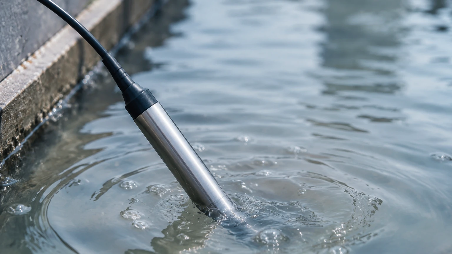
External light sources, such as direct sunlight or high-intensity overhead factory lights, can interfere with the sensor’s photodetector. This is especially true for immersion-style sensors in open tanks.
* Solution: Use light-shielding covers or ensure the sensor is submerged deep enough that ambient light cannot reach the sensing window.
Flow Velocity and Orientation
To prevent sediment buildup on the sensor face, a minimum flow velocity (typically 0.5 m/s) is recommended. However, excessively high velocity can cause cavitation and bubbles. The sensor should be oriented so that the optical window faces the flow to allow the moving liquid to provide a natural "self-cleaning" action.
Common Risks and Limitations
While highly effective, turbudity sensors have inherent limitations that must be managed through engineering controls:
1. Fouling and Biofilm: In wastewater or nutrient-rich environments, algae and biofilm can grow on the optical window. This "zero-shift" error makes the liquid appear more turbid than it actually is. Many modern sensors include mechanical wipers or ultrasonic cleaning systems to mitigate this.
2. Particle Size and Shape: Turbidity is a measure of light scatter, not mass. Two samples with the same mass of solids but different particle sizes (e.g., fine clay vs. coarse sand) will produce different NTU readings. Calibration must be performed using the actual process fluid if mass correlation is required.
3. Color Interference: As mentioned, colored liquids (like tea or industrial dyes) absorb light. If using a white-light sensor, this absorption will be misread as turbidity. Using infrared sensors (860nm) largely bypasses this issue.
Maintenance and Calibration Protocols
To maintain data integrity, a regular maintenance schedule is mandatory. Industrial sensors should be checked monthly for physical fouling and calibrated quarterly.
Calibration Standards
Formazin is the internationally recognized primary standard for turbidity calibration. However, because Formazin is toxic and has a short shelf life, many facilities use secondary standards, such as AMCO Clear (polymer beads) or stabilized Formazin.
* Zero Calibration: Use "turbidity-free" water, typically produced by passing distilled water through a 0.1μm filter.
* Slope Calibration: Use a standard that is near the high end of your expected process range.
Integration with Level Measurement Systems
In many industrial setups, turbidity and level measurement go hand-in-hand. For example, in a sedimentation tank, a hydrostatic level transmitter or an ultrasonic level sensor monitors the total volume of the tank, while the turbudity sensor monitors the clarity of the supernatant.
Welk provides a range of integrated solutions where level and water quality data are fed into a single PLC (Programmable Logic Controller). This allows for automated actions, such as closing an effluent valve if turbidity exceeds 1 NTU or initiating a backwash cycle in a sand filter based on head loss (measured by level) and turbidity breakthrough.
Frequently Asked Questions (FAQ)
Q: Can a turbidity sensor measure Total Suspended Solids (TSS)?
A: Yes, but only through correlation. You must take laboratory TSS measurements (mg/L) and compare them to the sensor's NTU readings over time to create a conversion curve specific to your process.
Q: What is the difference between NTU and FNU?
A: NTU (Nephelometric Turbidity Units) usually refers to measurements taken with a white light source (EPA 180.1), while FNU (Formazin Nephelometric Units) refers to measurements taken with an infrared light source (ISO 7027).
Q: How often should the sensor wiper be replaced?
A: In standard wastewater applications, wiper blades typically last 6 to 12 months. If the liquid contains abrasive particles or harsh chemicals, the interval may be shorter.
Q: Can these sensors be used in hazardous areas?
A: Yes, many industrial sensors are available with ATEX or IECEx certifications for use in explosive atmospheres, often utilizing intrinsically safe barriers or explosion-proof housings.
Conclusion
The implementation of a reliable turbudity sensor is a cornerstone of modern process automation. By understanding the optical principles of scattering and absorption, and by carefully considering installation factors like bubble interference and material compatibility, engineers can ensure long-term accuracy and minimal maintenance. Whether you are managing a municipal water plant or a complex chemical refinery, selecting the correct optical configuration is the first step toward optimized process control.
For more information on selecting the right level and process measurement technology for your specific industrial application, please visit our Main Page to explore our full suite of solutions.