Level Sensor Water
Level Sensor Water
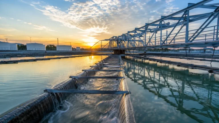
In industrial automation and process control, the accurate monitoring of water levels is a fundamental requirement. Whether managing municipal wastewater, cooling towers in power plants, or high-purity water in pharmaceutical manufacturing, selecting the appropriate level sensor water technology is critical for operational efficiency, safety, and regulatory compliance. This guide provides a technical overview of the primary measurement principles, selection criteria, and installation best practices for industrial water level instrumentation.
Understanding Water Level Measurement Principles
Before selecting a level sensor water, it is essential to understand the physics governing different measurement technologies. Most industrial applications utilize one of four primary methods: hydrostatic pressure, ultrasonic time-of-flight, radar (electromagnetic), or magnetic displacement.
Hydrostatic Level Measurement
Hydrostatic measurement is based on the principle that the pressure at a specific point in a liquid is proportional to the height of the liquid column above it. This relationship is defined by the formula:
P = ρ · g · h
Where:
* P is the hydrostatic pressure (Pa or kPa).
* ρ (rho) is the density of the water (kg/m³).
* g is the gravitational acceleration (approx. 9.81 m/s²).
* h is the height of the water column (m).
In practice, a submersible hydrostatic transmitter or a pressure sensor mounted at the bottom of a tank measures the pressure exerted by the water. Because the density of water is relatively constant (approximately 1,000 kg/m³ at 4°C), the pressure reading can be accurately converted into a level measurement. These sensors are highly effective for deep wells, boreholes, and large open reservoirs.
Ultrasonic Level Measurement
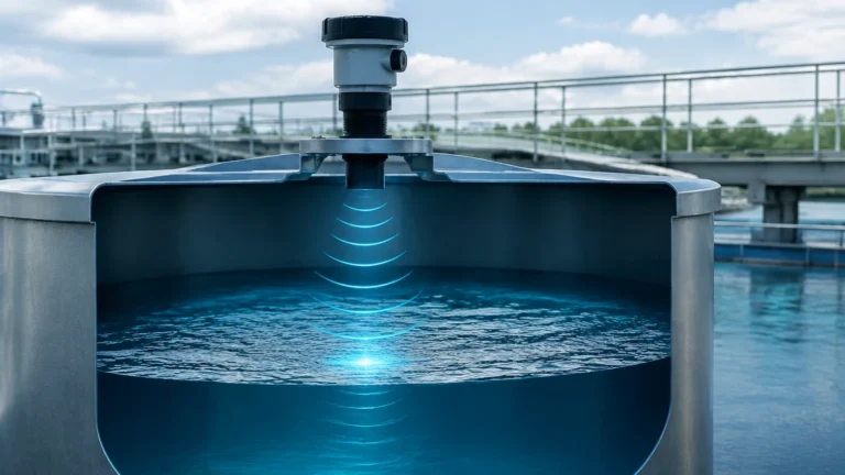
Ultrasonic sensors are non-contact devices that emit high-frequency sound waves (typically 20 kHz to 200 kHz) toward the water surface. The sensor measures the time it takes for the pulse to travel to the surface and return as an echo. The distance (D) is calculated as:
D = (c · t) / 2
Where c is the speed of sound in air and t is the transit time. The level is then derived by subtracting this distance from the known height of the tank. Ultrasonic sensors are ideal for wastewater and corrosive liquids where contact with the medium must be avoided.
Radar Level Measurement
Radar level meters operate similarly to ultrasonic sensors but use high-frequency electromagnetic waves (microwaves) instead of sound. There are two main types: Pulse Radar and Frequency Modulated Continuous Wave (FMCW) radar.
Because electromagnetic waves travel at the speed of light and are not significantly affected by air temperature, pressure, or vapor, radar provides higher precision than ultrasonic methods. This makes radar the preferred choice for industrial process tanks where steam, dust, or fluctuating temperatures are present.
Magnetic Level Gauges
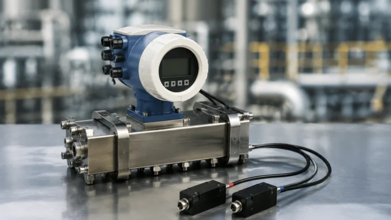
Magnetic level gauges utilize a float containing a permanent magnet. As the water level changes, the float moves along a bypass chamber or a guide tube. This movement either flips mechanical flags for visual indication or triggers reed switches/magnetostrictive sensors for a continuous electronic output. These are robust, mechanical solutions often used for boiler water or chemical storage where visual confirmation is required alongside electronic monitoring.
Key Selection Criteria for a Level Sensor Water
Choosing the right level sensor water depends on several technical factors. Engineers must evaluate the following parameters to ensure long-term reliability.
1. Water Characteristics
* Clean Water: Most technologies work well with potable or deionized water.
* Wastewater/Sludge: Requires non-contact sensors (ultrasonic/radar) or robust hydrostatic probes with large diaphragms to prevent clogging from solids and debris.
* Chemical Content: If the water contains acids or alkalis, the wetted parts of the sensor (e.g., PVDF, PTFE, or Stainless Steel 316L) must be chemically compatible.
2. Tank Geometry and Environment
* Open vs. Closed Tanks: Hydrostatic sensors in closed, pressurized tanks require a differential pressure setup to account for the headspace pressure.
* Internal Obstructions: In tanks with agitators, heating coils, or ladders, radar or ultrasonic sensors must be positioned carefully, or "false echo suppression" software must be used to ignore these fixed objects.
* Outdoor Installation: Sensors used in outdoor reservoirs must account for environmental factors like lightning protection, UV resistance, and condensation.
3. Required Accuracy and Range
For simple pump control in a sump, an accuracy of ±10mm (0.4 inches) may suffice. However, for custody transfer or precise chemical dosing, high-frequency radar sensors offering ±1mm to ±2mm accuracy are necessary. Measurement ranges can vary from a few centimeters in small flumes to over 200 meters (approx. 656 feet) in deep groundwater monitoring.
Comparative Analysis of Water Level Technologies
The following table summarizes the typical performance characteristics of common level sensor water technologies used in industrial applications.
| Technology | Typical Accuracy | Measurement Range | Contact Type | Best Applications |
| :— | :— | :— | :— | :— |
| Hydrostatic | ±0.1% to ±0.5% | 0.5m – 200m | Contact (Submerged) | Deep wells, open reservoirs, vented tanks |
| Ultrasonic | ±0.25% of range | 0.3m – 15m | Non-contact | Wastewater sumps, open channels, chemical tanks |
| Radar (80GHz) | ±1mm to ±5mm | 0.1m – 120m | Non-contact | Process vessels, high-precision storage, steam |
| Magnetic Float | ±5mm to ±10mm | 0.5m – 6m | Contact | Boiler water, oil-water separators, visual monitoring |
Installation Guidelines and Best Practices
Even the most advanced level sensor water will fail if installed incorrectly. Follow these engineering guidelines to ensure accurate readings.
Positioning and Mounting
* Avoid the Inflow: Never install a sensor directly under the water inlet. The turbulence and air entrainment from the incoming flow will cause unstable readings.
* The 1/6th Rule: For radar and ultrasonic sensors in cylindrical tanks, the ideal mounting position is often 1/6th of the diameter away from the tank wall. This avoids interference from wall reflections while staying clear of the center, where multiple reflections can occur.
* Stilling Wells: In applications with heavy turbulence or surface foam, installing the sensor inside a stilling well (a vertical pipe) can provide a calm surface for measurement.
Managing Condensation and Vapors
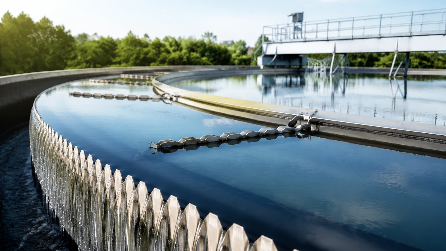
In water applications, condensation on the sensor face is a common issue.
* For ultrasonic sensors, condensation can dampen the signal. Choosing a sensor with a self-cleaning function or a higher power output can help.
* For radar, using a lens antenna or a PTFE-coated antenna allows droplets to slide off, maintaining signal integrity.
Cable Management for Hydrostatic Probes
When installing submersible hydrostatic transmitters, the cable usually contains a small vent tube to equalize the internal sensor pressure with atmospheric pressure. It is vital that this tube is not kinked or blocked. Using a moisture-trapping bellows or a specialized junction box with a breathable membrane is recommended to prevent water ingress into the vent tube.
Limitations and Mitigation Strategies
No single level sensor water is perfect for every scenario. Understanding the limitations is key to successful implementation.
1. Foam Interference: Heavy surface foam can absorb ultrasonic sound waves, leading to signal loss. In these cases, radar is generally more effective, although thick, dense foam may still require a stilling well.
2. Temperature Gradients: Ultrasonic sensors rely on the speed of sound, which changes with air temperature. Most modern ultrasonic sensors include an integrated temperature probe to compensate for this, but rapid temperature shifts can still cause transient errors.
3. Specific Gravity Variations: Hydrostatic sensors assume a constant water density. If the water contains high concentrations of dissolved solids or if the temperature fluctuates significantly (changing the density), the level reading will drift. If density is not constant, radar is a more reliable alternative.
Frequently Asked Questions (FAQs)
Q: How often should a level sensor water be calibrated?
A: For most industrial water applications, an annual calibration check is sufficient. However, in critical wastewater or chemical processes, a six-month interval may be required to check for build-up or corrosion on the sensor elements.
Q: Can ultrasonic sensors be used in vacuum tanks?
A: No. Ultrasonic waves require a medium (air or gas) to travel. In a vacuum, sound cannot propagate. Radar sensors should be used for vacuum applications as electromagnetic waves do not require a medium.
Q: What is the "blind zone" in ultrasonic and radar sensors?
A: The blind zone (or dead band) is the area directly below the sensor where it cannot accurately measure. This is due to the time required for the sensor to switch from transmitting to receiving mode. When selecting a sensor, ensure the maximum water level remains below the start of the blind zone.
Q: How do I protect outdoor sensors from lightning?
A: Industrial level sensors should be equipped with surge protection. For submersible probes, ensure the shield wire is properly grounded at the control panel, and consider using isolated barriers in areas prone to frequent storms.
Conclusion
Selecting a level sensor water involves a careful balance of technology, environment, and budget. While hydrostatic sensors offer a cost-effective solution for deep water monitoring, non-contact technologies like radar and ultrasonic provide the versatility needed for complex industrial processes. By understanding the measurement principles and following rigorous installation standards, facilities can ensure accurate and maintenance-free level control.
For comprehensive technical specifications and to explore various industrial models, users can visit the Main Page to find a solution tailored to specific hydraulic requirements. Welk provides a range of professional instruments designed to meet the rigorous demands of global industrial automation.