Level Transducers
Level Transducers
In the landscape of industrial process control, level transducers serve as the critical interface between physical material storage and digital monitoring systems. While the terms "sensor," "transmitter," and "transducer" are often used interchangeably in casual conversation, a transducer specifically refers to the device that converts one form of energy—such as mechanical pressure or ultrasonic echoes—into a standardized electrical signal. For engineers and procurement specialists, selecting the correct level transducers is essential for ensuring operational safety, inventory accuracy, and process efficiency.
Industrial level measurement is not a one-size-fits-all discipline. The choice of technology depends heavily on the physical properties of the media, the environmental conditions of the vessel, and the required precision of the data output. This guide provides a technical overview of the primary measurement principles, selection frameworks, and installation requirements for modern level measurement systems.
Understanding the Role of Level Transducers in Industrial Automation
Level transducers are deployed to monitor liquids, slurries, and granular solids within tanks, silos, and open channels. Their primary function is to provide continuous feedback to a Programmable Logic Controller (PLC) or Distributed Control System (DCS). Typically, these devices output a 4-20 mA analog signal, though digital protocols such as Modbus RS485, HART, and Foundation Fieldbus are increasingly common in "smart" industrial environments.
By converting physical levels into data, these instruments enable automated inventory management, prevent hazardous overfill conditions, and ensure that pumps do not run dry. For high-stakes applications in chemical processing or water treatment, the reliability of the transducer is the primary safeguard against systemic failure.
Core Measurement Principles and Technologies
To select the appropriate instrument, it is necessary to understand the underlying physics used to detect the surface of the material.
Hydrostatic Pressure Measurement
Hydrostatic level transducers operate on the principle that the pressure at the bottom of a liquid column is directly proportional to the height of the liquid above it, multiplied by the specific gravity of the fluid. The formula used is $P = \rho \cdot g \cdot h$, where $P$ is pressure, $\rho$ is density, $g$ is gravity, and $h$ is the height of the liquid.
These sensors are typically submerged at the bottom of a tank or mounted to a flange at the base. They are highly effective for vented tanks where atmospheric pressure is constant. However, if the tank is pressurized, a differential pressure (DP) transducer is required to subtract the headspace pressure from the total bottom pressure.
Ultrasonic (Time-of-Flight)
Ultrasonic transducers are non-contact devices that emit high-frequency sound pulses (usually between 20 kHz and 200 kHz). The pulse travels through the air, reflects off the surface of the media, and returns to the transducer. By measuring the time it takes for the echo to return, the device calculates the distance to the product.
Ultrasonic technology is cost-effective and easy to install because it does not touch the media. However, it is sensitive to air temperature fluctuations, heavy foam, and high-pressure vapors, all of which can attenuate or deflect the sound waves.
Radar (Microwave) Technology
Radar level transducers also use time-of-flight principles but utilize electromagnetic waves rather than sound. There are two primary types:
1. Guided Wave Radar (GWR): The microwave pulse travels along a physical probe or cable. This is ideal for low-dielectric liquids and applications with turbulence or foam.
2. Non-Contact Radar: The pulse is emitted through an antenna. High-frequency radar (e.g., 80 GHz) allows for narrow beam angles, making it suitable for tall, narrow tanks with internal obstructions.
Radar is generally considered the most robust technology for volatile environments, as it is unaffected by vacuum, high pressure, or temperature changes in the vapor space.
Magnetic and Float-Based Systems
Magnetic level gauges and float transducers use buoyancy to track the liquid level. A float containing a magnet moves along a sensing rod or interacts with an external visual indicator. These are highly reliable for high-temperature and high-pressure applications where electronic components must be isolated from the process media.
Technical Selection Criteria for Industrial Applications
When evaluating level transducers for a specific project, engineers must confirm several variables to avoid premature sensor failure or inaccurate readings.
1. Media Characteristics: Is the liquid corrosive, viscous, or prone to coating? For corrosive acids, PTFE-coated or non-contact sensors are required. For viscous liquids, flush-diaphragm hydrostatic sensors prevent clogging.
2. Process Conditions: What are the maximum operating pressures and temperatures? Standard ultrasonic sensors often fail above 70°C (158°F), whereas specialized radar or magnetic gauges can handle temperatures exceeding 400°C (752°F).
3. Tank Geometry: Internal structures like agitators, heating coils, or ladders can interfere with non-contact signals. In these cases, guided wave radar or hydrostatic sensors are often preferred.
4. Accuracy Requirements: For custody transfer or high-value chemical dosing, high-frequency radar offers millimeter-level precision. For general sump monitoring, a standard ultrasonic or hydrostatic sensor is usually sufficient.
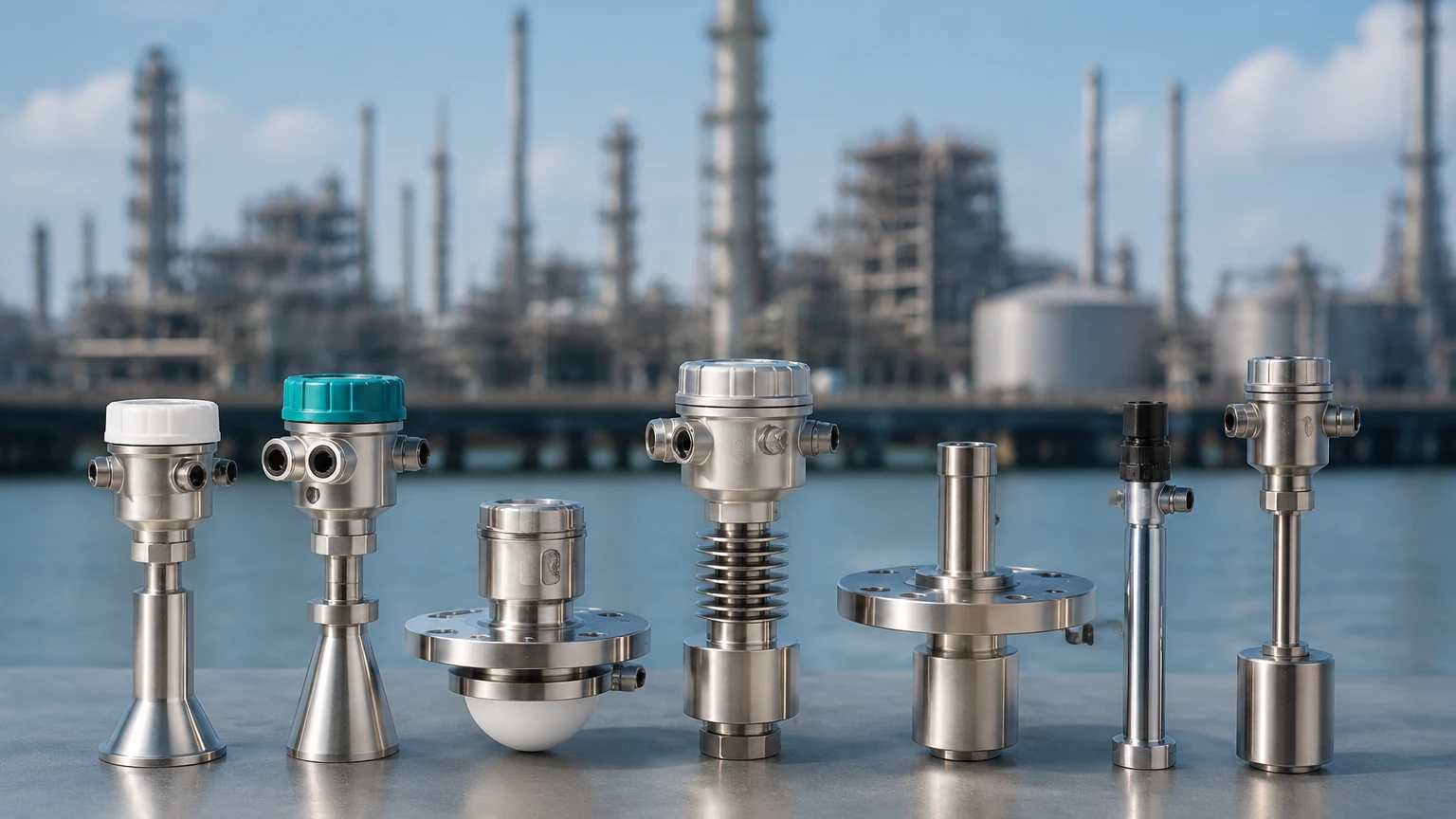
Comparative Analysis of Level Transducer Types
| Technology | Contact Type | Best For | Limitations | Typical Accuracy |
| :— | :— | :— | :— | :— |
| Hydrostatic | Contact | Vented tanks, deep wells | Sensitive to density changes | ±0.1% to ±0.5% |
| Ultrasonic | Non-contact | Water, wastewater, solids | Foam, dust, high pressure | ±0.25% of range |
| Radar (Non-contact) | Non-contact | Chemicals, high temp/pressure | High initial cost | ±1 mm to ±3 mm |
| Guided Wave Radar | Contact | Low dielectric fluids, foam | Probe can be coated/damaged | ±2 mm |
| Magnetic Float | Contact | High-pressure boilers, oil | Moving parts prone to wear | ±5 mm to ±10 mm |
Installation Guidelines and Best Practices
Proper installation is as critical as selecting the right technology. Even the most advanced level transducers will provide erratic data if mounted incorrectly.
Positioning and Orientation
For non-contact sensors (radar and ultrasonic), the transducer must be mounted perpendicular to the liquid surface. If the sensor is tilted, the signal may reflect away from the receiver, resulting in a "lost echo" error. Additionally, sensors should not be mounted in the center of a tank with a domed roof, as this can create multiple internal reflections that confuse the signal processing algorithm.
The Dead Zone (Blocking Distance)
Every ultrasonic and radar transducer has a "dead zone" directly beneath the sensor face where measurement is impossible. For an ultrasonic sensor, this might be 0.2 meters to 0.5 meters. Engineers must ensure that the maximum expected liquid level never enters this dead zone, or the sensor will report a full tank regardless of the actual level.
Avoiding Obstructions
When using beam-based technologies, ensure the signal path is clear of inflow pipes, ladders, and agitator blades. If obstructions are unavoidable, many modern transducers offer "false echo suppression" software, allowing the user to map out and ignore static reflections from internal tank hardware.
Environmental Protection
In outdoor installations, transducers should be equipped with sunshades to prevent overheating and localized temperature gradients. For hydrostatic sensors used in deep wells, vented cables must be protected against moisture ingress using desiccant cartridges to ensure accurate atmospheric pressure compensation.
Operational Limitations and Risk Mitigation
While modern level transducers are highly sophisticated, they are not immune to failure. Understanding the risks associated with each technology is vital for maintenance planning.
* Density Fluctuations: Hydrostatic transducers measure weight, not volume. If the temperature of the liquid changes significantly, its density changes, which will cause a hydrostatic sensor to report an incorrect level even if the volume remains the same.
* Vapor and Gas Layers: In chemical tanks, heavy vapors can slow down the speed of sound, causing ultrasonic sensors to over-report the distance (indicating a lower level than reality).
* Build-up and Scaling: Contact-based probes (GWR and floats) can suffer from material build-up. In wastewater applications, grease or scale can weigh down a float or short-circuit a capacitance probe. Regular cleaning cycles must be established for these environments.
Frequently Asked Questions (FAQs)
Q: Can I use one transducer for both liquids and solids?
A: Some technologies, like high-frequency radar, are versatile enough for both. However, solids often have an "angle of repose" (a sloped surface), which requires specific sensor positioning or a higher power output to ensure a reliable return signal.
Q: What is the difference between a 2-wire and 4-wire transducer?
A: A 2-wire transducer receives its power and transmits its 4-20 mA signal over the same pair of wires (loop-powered). A 4-wire transducer has separate pairs for power and signal, which is often necessary for power-intensive devices like heated sensors or long-range radar.
Q: How often should level transducers be calibrated?
A: For most industrial applications, an annual calibration check is recommended. However, in regulated industries like pharmaceuticals or food production, semi-annual or quarterly calibration may be required to meet safety standards.
Conclusion
Selecting the right level transducers requires a balance of theoretical knowledge and practical application experience. By understanding the physics of the measurement—whether it be the pressure of a liquid column or the flight time of a microwave—process engineers can design systems that are both accurate and resilient. For those looking to explore specific hardware configurations and technical specifications for their facility, you may Main Page to review product options and application support tailored to industrial requirements.
Whether the goal is to manage water treatment facilities or optimize chemical reactors, the integration of high-quality transducers is the first step toward achieving a fully optimized and automated process.