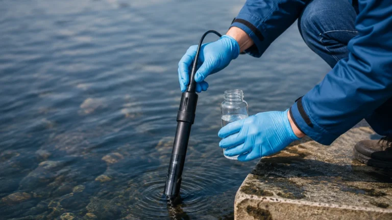
Lift Station Monitoring System
Lift Station Monitoring System
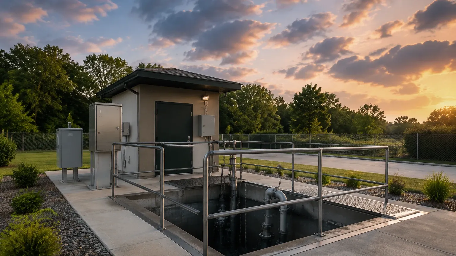
In municipal wastewater management and industrial fluid handling, lift stations serve as critical nodes that transport liquids from lower to higher elevations. Because these stations often operate in remote or underground locations, a robust lift station monitoring system is essential for maintaining operational continuity. Without accurate level measurement and real-time data acquisition, facilities risk pump failure, environmental contamination, and costly emergency overflows.
Modern monitoring systems rely on a combination of precise level sensors, intelligent controllers, and communication gateways to provide operators with a clear picture of wet well performance. This guide explores the core measurement principles, selection criteria, and installation best practices for engineering a reliable lift station monitoring solution.
Measurement Principles in Lift Station Monitoring
To select the right components for a lift station monitoring system, one must first understand the physics behind the level measurement technologies commonly employed in wet wells. Each method has distinct advantages depending on the fluid characteristics and environmental conditions.
1. Ultrasonic Level Measurement (Non-Contact)
Ultrasonic sensors operate on the "time-of-flight" principle. The sensor emits high-frequency sound pulses (typically between 20 kHz and 70 kHz) that travel through the air, reflect off the liquid surface, and return to the transducer. By measuring the time interval between transmission and reception, the system calculates the distance to the liquid level.
* Advantages: No contact with the medium prevents corrosion and fouling.
* Limitations: Performance can be degraded by heavy foam, high-density steam, or extreme turbulence, which can scatter or absorb the sound waves.
2. Radar Level Measurement (Non-Contact)
Radar sensors, specifically Frequency Modulated Continuous Wave (FMCW) or pulse radar, use electromagnetic waves instead of sound. These waves travel at the speed of light and reflect off the surface of the liquid based on the dielectric constant of the material.
* Advantages: Highly accurate (up to ±2 mm) and unaffected by temperature fluctuations, vacuum, pressure, or vapor. 80 GHz radar units are particularly effective in narrow lift stations due to their narrow beam angle.
* Limitations: Generally higher initial cost than ultrasonic or hydrostatic options.
3. Hydrostatic Pressure Measurement (Contact)
Hydrostatic level transmitters are submersible sensors that measure the pressure exerted by the liquid column above them. The pressure (P) is proportional to the height of the liquid (h) and its density (ρ), following the formula P = ρgh.
* Advantages: Simple installation and highly reliable in deep wells where foam or surface turbulence is a constant issue.
* Limitations: The sensor is in constant contact with the fluid. In wastewater, grease buildup or heavy sludge can clog the sensing diaphragm, requiring periodic cleaning.
4. Point Level Detection (Float Switches)
While not a continuous monitoring solution on its own, float switches are often integrated into a lift station monitoring system as redundant safety triggers. They provide high-level and low-level alarms to prevent dry running of pumps or tank overflows.
Key Components of a Monitoring System
A complete monitoring architecture consists of more than just a sensor. It requires an integrated stack of hardware and software to turn raw measurements into actionable data.
1. Primary Level Sensor: The radar, ultrasonic, or hydrostatic transmitter that provides the continuous 4-20mA or RS485 Modbus signal.
2. Pump Controller/RTU: A Remote Terminal Unit (RTU) or specialized pump controller that manages the start/stop cycles of the pumps based on the level data.
3. Communication Gateway: In remote lift stations, cellular (4G/5G), radio, or Ethernet gateways transmit data to a central SCADA system or a cloud-based dashboard.
4. Alarm System: Local visual/audible alarms and remote notifications (SMS/Email) for critical failure states.
For engineers looking to source high-quality instrumentation for these systems, the Main Page of professional manufacturers like Welk offers a wide array of radar and ultrasonic solutions tailored for industrial automation.
Selection Criteria for Lift Station Sensors
Choosing the right sensor for a lift station monitoring system depends on the specific challenges of the site. The following table provides a comparison for engineering reference:
| Feature | Ultrasonic Sensors | Radar (80 GHz) | Hydrostatic Transmitters |
| :— | :— | :— | :— |
| Measurement Type | Non-contact | Non-contact | Contact (Submerged) |
| Accuracy | ±0.25% of range | ±2 mm (0.08 in) | ±0.5% of span |
| Foam Resistance | Low | High | Excellent |
| Vapor/Steam Impact | High | Negligible | None |
| Grease/Fouling Risk | None | None | Moderate |
| Typical Range | 0.5m – 15m | 0.1m – 30m+ | 1m – 200m |
| Installation Ease | Moderate | Easy | Very Easy |
Evaluation Factors
* Fluid Composition: If the lift station handles heavy fats, oils, and grease (FOG), non-contact sensors (Radar/Ultrasonic) are preferred to minimize maintenance. If the surface is consistently covered in thick foam, radar or hydrostatic sensors are superior to ultrasonic.
* Well Geometry: Narrow wells with internal piping or ladders require sensors with narrow beam angles (like 80 GHz radar) to avoid false echoes from obstructions.
* Hazardous Locations: Many wastewater lift stations are classified as Class I, Div 1 or ATEX Zone 0 environments. Sensors must be intrinsically safe or explosion-proof.
Installation Considerations and Best Practices
Proper installation is as important as sensor selection. Even the most advanced lift station monitoring system will fail if the sensors are positioned incorrectly.
Positioning and Mounting
* Avoid the Inflow: Never mount a level sensor directly above the pipe where liquid enters the wet well. The resulting turbulence and splashing will cause erratic readings.
* Dead Zone (Blocking Distance): Ultrasonic sensors have a "dead zone" (typically 0.25m to 0.5m / 10in to 20in) directly below the transducer where they cannot measure. Ensure the sensor is mounted high enough that the maximum liquid level never enters this zone.
* Stilling Wells: In extremely turbulent wells, hydrostatic sensors should be installed inside a stilling well (a vertical pipe with vent holes) to protect the sensor from mechanical stress and provide a stable pressure reading.
Wiring and Surge Protection
Lift stations are often located in open areas prone to lightning strikes. Using shielded cables and installing surge protection devices (SPDs) on the 4-20mA loops can prevent expensive hardware damage during storms. For hydrostatic sensors, ensure the vent tube in the cable is protected by a desiccant filter to prevent moisture from entering the sensor housing and causing drift.
Limitations and Common Risks
While modern technology has greatly improved reliability, engineers must account for the following risks in a lift station monitoring system:
* Signal Loss due to Obstructions: In non-contact systems, buildup on the sensor face (spider webs, condensation, or grease) can attenuate the signal. Many high-end radar units now feature "self-cleaning" designs or software algorithms to ignore these obstructions.
* Power Outages: A monitoring system is useless without power. Incorporating a Battery Backup or Uninterruptible Power Supply (UPS) is standard practice for critical infrastructure.
* Communication Latency: In remote areas with poor cellular coverage, data may be delayed. Local logic (at the RTU level) should always be capable of managing the pumps independently of the central SCADA system to prevent overflows during a comms failure.
Frequently Asked Questions (FAQ)
Q: How often should lift station level sensors be calibrated?
A: Most modern digital sensors (Radar/Ultrasonic) are factory-calibrated and do not drift significantly. However, a manual check (comparing the sensor reading to a physical tape measure) should be performed every 6 to 12 months. Hydrostatic sensors may require more frequent zero-point checks if used in heavy sludge.
Q: Can I use one sensor to control multiple pumps?
A: Yes. A single continuous level sensor provides data to a controller, which then manages the lead/lag logic for multiple pumps. However, it is highly recommended to have a secondary high-level float switch as a redundant backup.
Q: What is the best sensor for a lift station with heavy foam?
A: Radar (80 GHz) is generally the best non-contact option because the high-frequency signal penetrates foam effectively. Hydrostatic sensors are also excellent as they measure from the bottom and are unaffected by surface conditions.
Q: How do I handle grease buildup on hydrostatic sensors?
A: Use a sensor with a large, flush-mounted diaphragm rather than a recessed one. Additionally, mounting the sensor in a location with some fluid movement (but not direct turbulence) can help prevent grease from settling on the face.
Conclusion
Implementing an effective lift station monitoring system requires a balanced approach to technology selection and installation engineering. By understanding the measurement principles of ultrasonic, radar, and hydrostatic technologies, operators can choose the most cost-effective and reliable solution for their specific environment. As industrial automation continues to evolve, the integration of high-precision sensors with remote monitoring capabilities ensures that lift stations remain a reliable part of our modern infrastructure. For further technical details on specific level measurement instruments, professionals are encouraged to review the product options and application support available on the Main Page of industry-leading suppliers.