Line Leak Detector
Line Leak Detector
In industrial fluid management, the integrity of piping systems is as critical as the storage vessels they connect. A line leak detector (LLD) is a specialized safety and monitoring device designed to detect unintended releases of product from pressurized or suction piping. Whether in water treatment, chemical processing, or oil and gas applications, these devices serve as the first line of defense against environmental contamination, financial loss, and hazardous conditions.
For engineers and facility managers, understanding the synergy between piping integrity and tank inventory is essential. While level measurement instruments provide data on the volume within a vessel, the line leak detector ensures that the transfer of that volume remains contained. To explore a comprehensive range of industrial measurement solutions, including those used in conjunction with leak detection systems, you may refer to our Main Page.
Understanding Line Leak Detection Principles
Line leak detection operates on several physical principles, primarily focused on monitoring changes in pressure, flow rates, or the presence of liquid where it should not be. The choice of principle depends on the piping type (pressurized vs. suction) and the required sensitivity.
Pressure Decay Method
This is the most common principle for pressurized lines. When a pump shuts off, the line leak detector monitors the "holding pressure" within the pipe. If the pressure drops faster than a calibrated rate, it indicates that fluid is escaping through a breach. In electronic systems, highly sensitive pressure transducers detect minute fluctuations that might be invisible to mechanical gauges.
Flow Comparison and Volumetric Analysis
In large-scale industrial automation, leak detection is often integrated into the control system. By comparing the flow rate at the pump discharge with the flow rate at the point of delivery, a discrepancy can be identified. Furthermore, by utilizing high-precision level sensors—such as those found on our Main Page—operators can perform a mass balance check. If the level in the source tank decreases by 500 liters but the receiving vessel only records an increase of 480 liters, a line leak is the likely culprit.
Mechanical Displacement
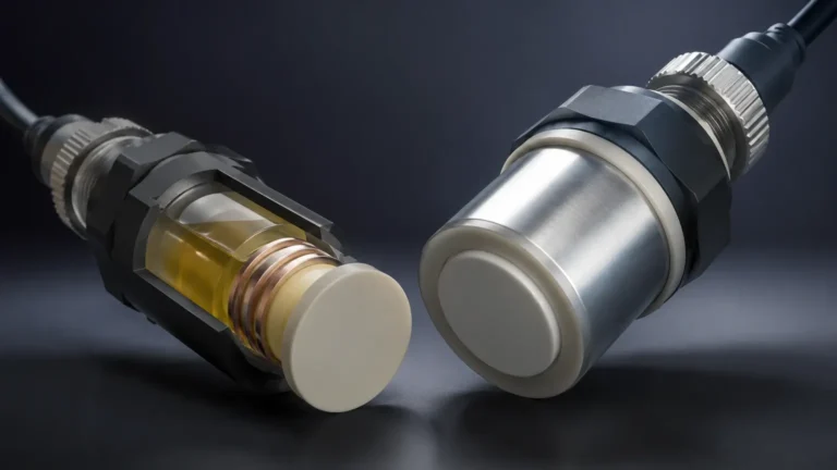
Mechanical line leak detectors often use a spring-loaded diaphragm or piston. When the pump starts, the device limits the flow to a small "test" volume. If the line reaches a specific pressure (indicating it is intact), the device opens fully. If the pressure fails to build because fluid is escaping, the device remains in a restricted flow mode (often called "slow-flow"), alerting the operator to a problem.
Types of Line Leak Detectors
Industrial leak detection is generally categorized into mechanical and electronic systems. Each has distinct advantages depending on the complexity of the facility.
Mechanical Line Leak Detectors (MLLD)
Mechanical units are favored for their simplicity and lack of power requirements. They are typically installed directly on the discharge head of a submersible pump.
* Pros: Cost-effective, no electrical wiring needed, intrinsically safe.
* Cons: Limited sensitivity (typically 11.4 liters per hour at 0.69 bar), cannot perform automated self-tests, and requires manual inspection.
Electronic Line Leak Detectors (ELLD)
Electronic systems use a microprocessor-based console and pressure transducers to monitor the lines. These are significantly more sensitive and can detect leaks as small as 0.38 liters per hour (0.1 gallons per hour).
* Pros: High sensitivity, programmable alarm thresholds, automatic pump shutdown, and digital logging for regulatory compliance.
* Cons: Higher initial cost, requires electrical power and professional calibration.
Technical Selection Criteria for Industrial Systems
Selecting the right line leak detector requires an evaluation of the fluid properties, pipe material, and operational environment. The following table provides a comparison for common selection factors:
| Feature | Mechanical LLD | Electronic LLD | Volumetric/Level-Based |
| :— | :— | :— | :— |
| Detection Sensitivity | ~11.4 L/h (3 GPH) | ~0.38 L/h (0.1 GPH) | Variable (System Dependent) |
| Fluid Compatibility | Limited by diaphragm material | High (Stainless steel sensors) | High (Non-contact sensors) |
| Response Action | Flow restriction | Alarm / Pump Shutdown | Data Log / System Alert |
| Maintenance | Annual functional test | Periodic calibration | Sensor cleaning/Verification |
| Ideal Application | Small fuel stations | Chemical plants, High-risk zones | Large bulk storage transfer |
Material Compatibility
In chemical and water treatment industries, the line leak detector must be compatible with the media. For corrosive fluids, PTFE-coated diaphragms or 316L stainless steel housings are required. For standard petroleum applications, Buna-N or Viton seals are common.
Pipe Length and Volume
Every leak detector has a maximum "dead head" volume it can accurately test. If the piping run is excessively long (e.g., over 150 meters), the elasticity of the pipe and the thermal expansion of the fluid can interfere with pressure-based readings. In these cases, specialized high-volume ELLDs are necessary.
Integrating Level Measurement and Leak Detection
A robust leak detection strategy does not rely on line sensors alone. It integrates data from the entire storage system. Level measurement instruments play a vital role in this ecosystem.
1. Static Leak Detection: When the system is idle, radar or ultrasonic level meters monitor the tank level. If the level drops without any authorized discharge, it indicates a leak in either the tank or the connected piping (if the valves are open).
2. Hydrostatic Pressure Monitoring: Hydrostatic transmitters can detect changes in head pressure that might indicate a slow weep in a line that is otherwise pressurized by the tank's gravity head.
3. Redundancy: Using level switches as high-level and low-level alarms provides a secondary check. If a line leak detector fails to trip but the tank level hits a low-level alarm prematurely, the system can trigger an emergency shutdown.
For detailed specifications on the sensors that facilitate this integration, visit the Main Page.

Installation and Calibration Best Practices
Proper installation is paramount to preventing false alarms and ensuring the line leak detector functions when needed.
* Positioning: Mechanical LLDs must be installed vertically on the pump discharge. Electronic transducers should be placed where they are protected from physical damage but accessible for calibration.
* Air Elimination: Air trapped in the piping is the most common cause of false leak indications. Because air is compressible, it prevents the pressure from stabilizing during a leak test. High-point vent valves should be used to ensure the line is "liquid full."
* Thermal Stabilization: Large temperature swings can cause fluid to expand or contract. If a test is performed immediately after a delivery of cold fluid into a warm pipe, the resulting pressure drop may be mistaken for a leak. Advanced electronic detectors include thermal compensation algorithms to mitigate this.
* Calibration: Electronic systems should be calibrated annually using a simulated leak. This involves bleeding off a measured amount of fluid (e.g., 380 ml) to ensure the sensor triggers the alarm within the required timeframe.
Operational Limitations and Environmental Factors
While highly effective, line leak detectors are not infallible. Engineers must account for the following limitations:
* Vapor Pressure: Highly volatile liquids with high vapor pressures can create gas pockets in the line, leading to erratic pressure readings.
* Pipe Elasticity: Flexible piping (such as certain plastics) expands under pressure more than steel. This "creep" can mimic the pressure drop of a leak during the first few seconds of a test.
* Suction Lines: Standard LLDs are designed for pressurized systems. Suction lines (where the pump is at the end of the line) require different technology, such as vacuum monitoring or interstitial monitoring in double-walled pipes.
Frequently Asked Questions (FAQ)
Q: How often should a line leak detector be tested?
A: Most regulatory bodies and manufacturers recommend a functional test at least once a year. In high-risk chemical applications, semi-annual testing is preferred to ensure the safety of the automation system.
Q: Can a line leak detector find a leak in a suction line?
A: Standard pressure-based LLDs cannot. Suction lines typically use a check valve at the tank (foot valve). If the line leaks, the fluid drains back into the tank, and the pump loses its prime. Monitoring for loss of prime or using vacuum-based interstitial sensors is the standard approach for suction systems.
Q: Why does my electronic leak detector trigger an alarm when there is no leak?
A: The most common causes are trapped air, faulty check valves at the pump, or extreme temperature changes. If the check valve leaks back into the tank, the line pressure will drop, and the ELLD will interpret this as a leak to the environment.
Q: Does the viscosity of the fluid affect leak detection?
A: Yes. Highly viscous fluids move slower through a breach. A mechanical leak detector calibrated for thin fluids like gasoline may not respond correctly to heavy oils or thick resins without recalibration of the spring tension and orifice size.
Conclusion
Implementing a reliable line leak detector is a critical component of modern industrial fluid handling. By understanding the underlying physics—whether it be pressure decay or volumetric comparison—and integrating these devices with high-quality level measurement instruments, facilities can achieve a high standard of safety and operational efficiency. For more information on the instrumentation required to build a complete monitoring solution, please visit our Main Page.