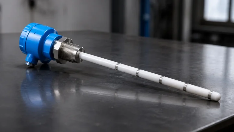
Line Monitoring
Line Monitoring
In industrial process control, line monitoring refers to the continuous oversight of signal integrity and physical conditions within a measurement loop. For level measurement applications, effective line monitoring ensures that the data transmitted from a field sensor—such as a radar or ultrasonic transmitter—to a Programmable Logic Controller (PLC) or Distributed Control System (DCS) is both accurate and uninterrupted. This practice is essential for preventing overflows, protecting pumps from dry-running, and maintaining safety standards in chemical, water treatment, and oil and gas facilities.
Reliable line monitoring involves more than just checking for a signal; it requires an understanding of the measurement principles of the instruments involved and the diagnostic capabilities of the communication protocols used. By implementing robust monitoring strategies, engineers can distinguish between a genuine low-level reading and a fault in the transmission line.
Measurement Principles and Signal Integration
Before selecting a strategy for line monitoring, it is necessary to understand how different level measurement technologies generate and transmit data. Each technology interacts with the monitoring system differently based on its physical operating principle.
Radar Level Measurement
Radar transmitters, including both Guided Wave Radar (GWR) and Non-Contact Radar, utilize electromagnetic pulses or continuous waves to detect levels. In Frequency Modulated Continuous Wave (FMCW) radar, the transmitter emits a high-frequency signal that increases linearly over time. The reflection from the product surface is received, and the frequency difference between the emitted and received signal is proportional to the distance.
From a line monitoring perspective, radar systems are highly advantageous because they often include sophisticated internal diagnostics. They can monitor the amplitude of the "echo" and the health of the microwave electronics. If the signal is lost due to heavy foam or a hardware failure, the device can drive the output to a specific fault current (e.g., 3.6 mA or 21 mA) to alert the control system.
Ultrasonic Level Sensors
Ultrasonic sensors use piezoelectric transducers to emit sound waves, typically in the range of 20 kHz to 200 kHz. The sensor measures the time-of-flight for the sound wave to travel to the surface and back. Because the speed of sound is affected by air temperature, these sensors usually include an integrated temperature probe for compensation.
Line monitoring for ultrasonic devices must account for environmental factors. For example, if a signal is lost due to excessive turbulence or steam, the monitor must be able to identify this as a "Lost Echo" condition rather than a physical line break. Modern ultrasonic transmitters provide specific error codes via digital protocols to facilitate this distinction.
Hydrostatic Level Transmitters
Hydrostatic sensors measure the pressure exerted by a liquid column, which is directly proportional to the height of the liquid based on the formula $P = \rho gh$ (where $P$ is pressure, $\rho$ is density, $g$ is gravity, and $h$ is height). These are typically submerged or flange-mounted at the bottom of a tank.
For hydrostatic sensors, line monitoring often focuses on the integrity of the vent tube in the cable. This tube allows the sensor to compensate for changes in atmospheric pressure. If the vent tube becomes blocked or moisture enters it, the level reading will drift. Monitoring systems look for sudden, unrealistic shifts in pressure to identify these mechanical line failures.
Key Evaluation Criteria for Line Monitoring
When evaluating a level measurement solution for its line monitoring capabilities, engineers should focus on the following criteria to ensure long-term reliability:
1. Diagnostic Depth: Does the instrument comply with NAMUR NE43 standards? This standard defines how a 4-20 mA signal should behave during a fault, allowing the monitoring system to distinguish between a valid 4 mA (0% level) and a 3.6 mA (sensor failure).
2. Communication Protocol: Digital protocols like HART (Highway Addressable Remote Transducer), Modbus RS-485, or Foundation Fieldbus provide significantly more line monitoring data than a simple analog loop. They allow for the transmission of secondary variables, such as internal device temperature or signal strength.
3. Update Rate: In fast-moving processes, the frequency at which the line is polled for data is critical. High-speed line monitoring ensures that a sudden pipe burst or valve failure is detected in milliseconds rather than seconds.
4. Redundancy: In high-risk applications, using two different technologies (e.g., radar and a magnetic level gauge with a transmitter) provides a secondary form of line monitoring. If the two readings diverge, a fault is flagged.
Technology Selection Table
The following table compares common level measurement technologies and their inherent strengths regarding line monitoring and diagnostic feedback.
| Technology | Measurement Principle | Line Monitoring Benefit | Ideal Application |
| :— | :— | :— | :— |
| Radar (FMCW) | Electromagnetic Wave | High-resolution diagnostics; signal strength monitoring. | Chemical tanks with vapor/agitation. |
| Ultrasonic | Sound Wave (Time-of-Flight) | Detects "Lost Echo" conditions; non-contact safety. | Water treatment and open channels. |
| Hydrostatic | Pressure Differential | Direct monitoring of liquid head; simple 2-wire loop. | Deep wells and vented tanks. |
| Magnetic Gauge | Buoyancy & Magnetism | Visual backup provides physical line verification. | High-pressure boilers and oil tanks. |
| Level Switch | Vibration/Frequency | Point-level monitoring; simple fail-safe logic. | Overfill protection and pump dry-run. |
For a comprehensive overview of available instrumentation and technical specifications, engineers can visit the Main Page to review product options and application support.
Installation Considerations for Signal Integrity
The physical installation of the cabling and the instrument is the foundation of effective line monitoring. Even the most advanced sensor will fail to provide reliable data if the transmission line is compromised by poor installation.
Shielding and Grounding
Electromagnetic Interference (EMI) is a common cause of signal "noise" that can trigger false alarms in a line monitoring system. All signal cables should be shielded, and the shield should typically be grounded at only one end (usually the control room side) to prevent ground loops. In environments with heavy motors or VFDs (Variable Frequency Drives), using twisted-pair cabling is essential to cancel out induced noise.
Loop Resistance and Power Supply
For 4-20 mA current loops, the total resistance of the line (including the cable resistance and the input impedance of the PLC) must not exceed the driving capability of the transmitter’s power supply. If the resistance is too high, the current will be unable to reach 20 mA, leading to inaccurate high-level readings. Line monitoring systems should include a check for loop voltage to ensure the transmitter has sufficient power to operate under all conditions.
Environmental Protection
In outdoor or wash-down environments, moisture ingress into junction boxes is a primary cause of line failure. Using IP67 or IP68 rated connectors and ensuring that cable glands are properly tightened are critical steps. For hydrostatic sensors, the use of desiccant filters on the atmospheric vent tube is recommended to prevent condensation from forming inside the sensor body.

Limitations and Risk Mitigation
While line monitoring significantly improves process safety, it is not without limitations. Engineers must be aware of these constraints to design a truly resilient system.
* Signal Attenuation: In very long cable runs (exceeding 1,000 meters), signal degradation can occur. For such distances, digital communication like RS-485 or converting the signal to fiber optics is preferred over standard analog loops.
* False Positives: Highly sensitive line monitoring may trigger alarms due to transient spikes or temporary environmental interference. Implementing a "damping" or "delay" factor in the control logic can help filter out non-critical fluctuations while still responding to genuine failures.
* Mechanical vs. Electronic Failure: Line monitoring is excellent at detecting electronic faults (broken wires, short circuits) but may not always detect mechanical issues, such as a build-up of material on a radar antenna or a stuck float in a magnetic gauge. Regular physical inspection remains a necessary component of a maintenance program.
Frequently Asked Questions (FAQ)
Q: How does line monitoring distinguish between an empty tank and a broken wire?
A: This is primarily achieved through the use of the 4-20 mA standard. An empty tank is typically represented by 4 mA. A broken wire results in 0 mA. By setting the PLC to trigger a "Fault" alarm whenever the current drops below 3.8 mA, the system can immediately identify a line break.
Q: Can line monitoring detect a leak in a process pipe?
A: While electrical line monitoring detects signal faults, hydrostatic level sensors can be used for physical line monitoring. A sudden drop in level that does not correlate with valve positions or pump activity can indicate a leak in the process line.
Q: What is the maximum distance for a monitored signal line?
A: For a standard 4-20 mA loop, the distance is limited by the wire gauge and the power supply voltage, often reaching up to 1,500 meters (approx. 4,900 feet). For digital monitoring via Modbus RS-485, the limit is typically 1,200 meters (approx. 3,900 feet) before repeaters are required.
Q: Does HART protocol improve line monitoring?
A: Yes. HART allows the transmitter to send detailed diagnostic data digitally over the same two wires used for the 4-20 mA signal. It can report specific errors like "Sensor Crystal Failure" or "Supply Voltage Low," which are impossible to communicate via analog signals alone.
Q: How often should line monitoring systems be calibrated?
A: While the monitoring logic itself doesn't require frequent calibration, the instruments providing the data should be verified annually. Loop testing, where a known signal is injected at the sensor end to verify the reading at the PLC, should be part of the standard preventive maintenance schedule.