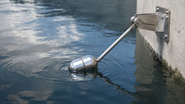
Liquid Flow Switch
Liquid Flow Switch
In industrial process control, the ability to detect the presence or absence of flow is as critical as measuring the exact volume of liquid passing through a pipe. A liquid flow switch serves as a fundamental safety and automation component, designed to provide a discrete output—typically a relay or transistor signal—when a specific flow rate threshold is reached. Unlike continuous flow meters that provide a constant stream of data, a flow switch acts as a sentinel, protecting expensive equipment like pumps and heat exchangers from damage caused by low-flow or no-flow conditions.
For engineers and facility managers, selecting the correct liquid flow switch requires a deep understanding of fluid dynamics, material science, and the specific mechanical principles that drive these devices. This guide provides a technical overview of liquid flow switch technologies, selection criteria, and installation best practices to ensure long-term operational reliability.
Measurement Principles of Liquid Flow Switches
Before selecting a device for an industrial application, it is essential to understand the physics behind the sensing element. Most industrial switches fall into three primary categories: mechanical, thermal, and ultrasonic.
1. Mechanical (Paddle and Vane) Switches
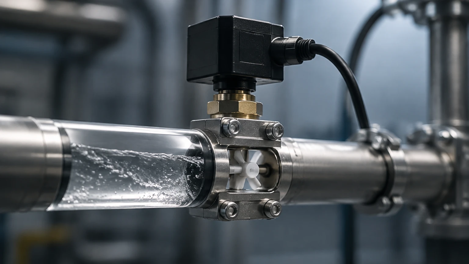
Mechanical flow switches are the most common and traditional type. They utilize a paddle or vane suspended in the fluid stream. As the liquid moves, it exerts a dynamic force against the paddle. When the flow reaches a certain velocity, the force overcomes a spring or gravity-loaded mechanism, moving the paddle and triggering a microswitch or magnetic reed switch.
* Advantages: Simple design, low cost, and no power requirement for the sensing element itself (though the output circuit requires power).
* Limitations: Moving parts are susceptible to wear, and the paddle can become fouled by debris or high-viscosity fluids.
2. Thermal Dispersion Switches
Thermal dispersion technology relies on the principle of heat transfer. The sensor probe contains two thermistors: one is heated, and the other remains at the process temperature. As liquid flows past the heated probe, it carries away heat. The temperature difference between the two thermistors is inversely proportional to the flow velocity. An integrated circuit monitors this difference and triggers the switch when the flow drops below or rises above the set point.
* Advantages: No moving parts, high reliability in contaminated liquids, and the ability to detect very low flow rates.
* Limitations: Sensitive to changes in the thermal conductivity of the fluid and significant temperature fluctuations.
3. Piston or Shuttle Switches
In these devices, a piston is housed within a chamber. The flow of liquid forces the piston to move against a calibrated spring. A magnet embedded in the piston actuates a reed switch located outside the flow path. These are often used in high-pressure systems and small-diameter piping.
* Advantages: Excellent repeatability and high pressure ratings.
* Limitations: High pressure drop across the device and sensitivity to particulates that can jam the piston.
Key Evaluation Criteria for Selection
Selecting a liquid flow switch is not a "one size fits all" process. Engineers must evaluate several variables to ensure the device performs within the intended parameters of the Main Page of their system design.
Fluid Properties
* Viscosity: High-viscosity liquids (e.g., heavy oils) increase the drag on mechanical switches, potentially causing false trips. Thermal switches may require recalibration for fluids with different thermal properties.
* Corrosivity: The wetted materials must be compatible with the media. While 316L stainless steel is standard, aggressive chemicals may require Hastelloy, Monel, or plastic bodies like PVC or PVDF.
* Cleanliness: If the liquid contains solids or slurry, mechanical switches with paddles or pistons are likely to fail. In these cases, non-intrusive or thermal dispersion models are preferred.
Operating Environment
* Pressure and Temperature: Ensure the switch body and seals (O-rings) can withstand the maximum system pressure (expressed in bar or PSI) and temperature (Celsius or Fahrenheit). Standard industrial switches often handle up to 100 bar (1450 PSI).
* Flow Range: Determine the "set point"—the specific flow rate where the switch must trigger. Check the manufacturer's data for the minimum and maximum flow velocities the switch can detect.
Electrical Requirements
* Output Type: Most switches offer a SPDT (Single Pole Double Throw) relay, but solid-state outputs (NPN/PNP) are common for high-speed switching or PLC integration.
* Certifications: Applications in hazardous areas require ATEX, IECEx, or UL explosion-proof ratings.
Practical Selection Table
The following table compares the three most common liquid flow switch technologies based on typical industrial requirements.
| Feature | Paddle / Vane | Thermal Dispersion | Piston / Shuttle |
| :— | :— | :— | :— |
| Moving Parts | Yes | No | Yes |
| Pressure Drop | Low | Negligible | Moderate to High |
| Dirty Liquids | Poor | Excellent | Poor |
| Low Flow Sensitivity | Moderate | High | Moderate |
| Maintenance | Regular | Minimal | Regular |
| Typical Application | Water pipes > 50mm | Chemical dosing, Cooling | Lubrication lines, High pressure |
Installation Considerations and Best Practices
Proper installation is the single most important factor in the accuracy and longevity of a liquid flow switch. Even the highest-quality sensor will fail if placed in a turbulent or improperly oriented section of piping.
1. Straight Pipe Requirements
To ensure a stable flow profile, switches should be installed in a straight run of pipe. A general rule of thumb is to have at least five pipe diameters (5D) of straight pipe upstream and three pipe diameters (3D) downstream of the switch. This minimizes turbulence caused by elbows, valves, or pumps.
2. Orientation
* Horizontal Pipes: This is the ideal orientation. For mechanical switches, the sensor should usually be mounted on the top of the pipe to prevent sediment from interfering with the mechanism.
* Vertical Pipes: If installing in a vertical line, the flow must be in an upward direction. This ensures the pipe is completely full of liquid and prevents gravity from causing the paddle or piston to drop prematurely. Downward flow is generally discouraged as it can lead to air pockets and inconsistent switching.
3. Avoiding Air Pockets and Cavitation
The sensor must always be fully submerged in the liquid. Avoid installing switches at the highest point of a piping system where air can trap, or immediately after a pump where cavitation might occur. Air bubbles passing through a thermal dispersion switch can cause rapid, false temperature readings, leading to "chattering" of the relay.
4. Wiring and Interference
For electronic switches (thermal or ultrasonic), ensure that signal cables are shielded and separated from high-voltage power lines to prevent electromagnetic interference (EMI). Always verify that the supply voltage matches the device specifications (e.g., 24V DC vs. 230V AC).
Common Risks and Limitations
While liquid flow switches are robust, they are not infallible. Awareness of their limitations can prevent system downtime.
* Scaling and Buildup: In hard water applications, calcium carbonate or other minerals can build up on the sensor. For a thermal switch, this acts as insulation, slowing the response time. For a paddle switch, it can increase the weight of the paddle, changing the set point.
* Turbulence: If a switch is placed too close to a pump or a partially closed valve, the resulting turbulence can cause the switch to oscillate between "on" and "off" states. This can be mitigated by using a switch with a built-in time delay or increasing the straight pipe run.
* Viscosity Shifts: If the process temperature drops significantly, the viscosity of the liquid may increase. This change in fluid thickness exerts more force on mechanical components, potentially triggering a "high flow" signal even when the actual velocity has not changed.
Industrial Applications
Liquid flow switches are utilized across diverse sectors to ensure process integrity:
* Pump Protection: Perhaps the most common use. If a pump runs dry (without liquid), the friction generates heat that can destroy seals and impellers within minutes. A flow switch installed on the discharge side can shut down the pump if flow is lost.
* Chiller and Heat Exchanger Monitoring: In HVAC and industrial cooling, a flow switch ensures that coolant is circulating before the compressor or heating element engages. This prevents freezing or overheating of the heat exchanger tubes.
* Chemical Dosing: In water treatment, flow switches confirm that the main water line is moving before chemical injection pumps are activated, preventing dangerous concentrations of chemicals in stagnant water.
* Lubrication Systems: Large turbines and gearboxes require a constant flow of oil. Flow switches monitor these lubrication lines to prevent catastrophic mechanical failure.
Frequently Asked Questions (FAQs)
Q: Can a liquid flow switch be used to measure the exact flow rate?
A: No. A flow switch is a discrete device that tells you if the flow is above or below a certain point. To measure the exact flow rate (e.g., 15.5 liters per minute), you need a flow transmitter or flow meter.
Q: What is the difference between a "normally open" (NO) and "normally closed" (NC) contact?
A: In a "normally open" configuration, the circuit is open (no current flows) when there is no flow. When flow starts, the switch closes. In a "normally closed" configuration, the circuit is closed when there is no flow and opens when flow is detected. Most industrial switches provide both options via a SPDT relay.
Q: How do I handle a situation where the flow rate is very close to the set point?
A: This can cause the switch to "chatter" (rapidly open and close). Look for a switch with adjustable hysteresis or a built-in dampening/time-delay feature. This allows the flow to drop slightly below the set point before the switch resets.
Q: Are thermal flow switches better than paddle switches?
A: Not necessarily. Thermal switches are better for dirty liquids, low flow rates, and applications where maintenance access is difficult. However, paddle switches are often more cost-effective for large water pipes and do not require sophisticated electronics.
Conclusion
The liquid flow switch is a vital component in the hierarchy of industrial instrumentation. Whether protecting a multi-million dollar cooling system or ensuring the correct dosage of chemicals in a treatment plant, the reliability of the switch depends on matching the technology to the application. By considering fluid characteristics, pipe geometry, and environmental factors, engineers can implement a solution that provides years of trouble-free service. For those looking to integrate these sensors into broader automation frameworks, reviewing the latest specifications and Main Page product options is a recommended next step in the procurement process.