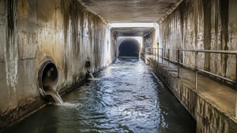
Liquid Level Control
Liquid Level Control
In industrial process automation, liquid level control is a fundamental requirement for ensuring operational safety, process efficiency, and product quality. Whether managing water treatment facilities, chemical processing plants, or oil and gas storage, the ability to accurately monitor and regulate the volume of liquids in tanks and vessels is critical. Effective liquid level control prevents hazardous overflows, protects pumps from running dry, and ensures that chemical reactions occur within precise volumetric parameters.
This guide provides a comprehensive technical overview of liquid level control systems, the physical principles underlying measurement technologies, and practical considerations for selecting and installing the appropriate instrumentation for industrial environments.
Understanding the Fundamentals of Liquid Level Control
At its core, a liquid level control system consists of three primary components: a sensing element, a controller, and a final control element (such as a valve or pump). The process begins with the sensor detecting the current level of the liquid and converting this physical state into an electrical signal—typically a 4-20mA analog output or a digital communication protocol like HART or Modbus.
The controller (often a PLC, DCS, or a dedicated level controller) compares the measured value against a predefined setpoint. Based on the deviation, the controller sends a command to the final control element to either add liquid to the vessel or discharge it.
There are two main types of control logic used in these systems:
1. Point Level Control (On/Off): This is used for simple tasks like high-level alarms or low-level pump protection. When the liquid reaches a specific point, a switch is triggered to open or close a circuit.
2. Continuous Level Control: This provides real-time data across the entire height of the tank. It allows for sophisticated modulation of flow rates, which is essential for maintaining steady-state conditions in complex chemical or pharmaceutical processes.
Core Measurement Principles and Technologies
Before selecting a system for liquid level control, it is essential to understand the physics behind the various measurement technologies. Each method has specific strengths and limitations based on the properties of the liquid and the environmental conditions of the vessel.
Radar Level Measurement
Radar level meters utilize electromagnetic waves to measure distance. There are two primary types: Pulse Radar and Frequency Modulated Continuous Wave (FMCW). In both cases, the sensor emits a microwave signal that reflects off the liquid surface and returns to the receiver. By measuring the time-of-flight or frequency shift, the instrument calculates the distance to the liquid.
* Advantages: Non-contact measurement, unaffected by density, pressure, or temperature changes. High-frequency radar (e.g., 80GHz) offers narrow beam angles, making it ideal for vessels with internal obstructions.
* Limitations: Highly turbulent surfaces or very low dielectric constant (εr) liquids can reduce signal reflection strength.
Ultrasonic Level Sensors
Ultrasonic sensors function similarly to radar but use sound waves instead of electromagnetic waves. The sensor emits a high-frequency pulse that travels through the air, hits the liquid surface, and echoes back.
* Advantages: Cost-effective and easy to install. Suitable for a wide range of non-corrosive and corrosive liquids in open channels or vented tanks.
* Limitations: Sound speed is affected by air temperature and vapor composition. They are generally not recommended for vacuum applications or high-pressure vessels where the medium through which the sound travels changes significantly.
Hydrostatic Level Transmitters
This technology relies on the principle that the pressure at the bottom of a liquid column is directly proportional to its height and density ($P = \rho \cdot g \cdot h$). A pressure sensor is placed at the bottom of the tank or submerged in the liquid.
* Advantages: Simple, reliable, and excellent for deep wells or underground tanks.
* Limitations: Accuracy depends on a constant liquid density. If the temperature fluctuates significantly or if the liquid composition changes, the level reading will drift unless density compensation is applied.
Magnetic Level Gauges
Magnetic gauges use a float containing a permanent magnet that moves with the liquid level inside a bypass chamber. Outside the chamber, a series of magnetic flags or a sensing probe tracks the position of the float.
* Advantages: Provides a clear visual indication without requiring power. Can be equipped with transmitters for remote liquid level control.
* Limitations: Mechanical components are subject to wear, and the float can become stuck if the liquid contains high levels of particulates or becomes overly viscous.
Selecting the Right Technology for Your Application
Choosing the correct instrument for liquid level control requires a detailed analysis of the process media and the vessel geometry. The following table provides a general comparison of common technologies used in industrial settings.
| Technology | Media Type | Measuring Range | Typical Accuracy | Pressure/Temp Resistance |
| :— | :— | :— | :— | :— |
| Radar | Liquids, Slurries | Up to 100m (328 ft) | ±1mm to ±3mm | Excellent (High P/T) |
| Ultrasonic | Clean Liquids | Up to 15m (49 ft) | ±0.25% of range | Moderate |
| Hydrostatic | Water, Oils | Up to 200m (656 ft) | ±0.1% to ±0.5% | Good (Submersible) |
| Magnetic | Clean Liquids | Up to 6m (20 ft) | ±5mm to ±10mm | Good |
When evaluating these options, engineers should consult the Main Page of the equipment manufacturer to review specific model specifications and chemical compatibility charts.
Implementation and Installation Best Practices
Even the most advanced sensor will fail to provide accurate liquid level control if it is installed incorrectly. Proper placement is the most significant factor in long-term reliability.
Avoiding Obstructions
For non-contact sensors like radar and ultrasonic, the "beam path" must be clear. Internal structures such as ladders, heating coils, or agitators can create "false echoes." While many modern instruments feature software for false-signal suppression, it is best practice to install the sensor at least 300mm (12 inches) away from the tank wall and away from the fill stream to avoid turbulence.
The Dead Zone (Blocking Distance)
Every ultrasonic and radar sensor has a "dead zone" or "blocking distance" directly beneath the sensor face where measurement is impossible. If the liquid level enters this zone, the sensor may report a full tank or an error. Always ensure the sensor is mounted high enough so that the maximum liquid level never reaches the minimum blocking distance.
Environmental Protection
In outdoor installations, sensors should be protected from direct sunlight to prevent temperature-induced measurement errors (especially for ultrasonic units). In chemical environments, the wetted parts of the sensor (the parts in contact with the liquid or vapors) must be made of compatible materials such as PVDF, PTFE, or 316L Stainless Steel.

Common Risks and Mitigation Strategies
Implementing a system for liquid level control involves managing several operational risks that can lead to system failure or inaccurate data.
1. Foam and Turbulence: Thick foam on the surface of a liquid can absorb ultrasonic and radar signals, leading to signal loss. In these cases, hydrostatic transmitters or guided wave radar (GWR) are often preferred because they are less affected by surface conditions.
2. Build-up and Scaling: In wastewater or mining applications, material can build up on the sensor face. Non-contact radar is generally more resistant to this, but periodic maintenance and cleaning schedules should be established.
3. Vapor and Condensation: Heavy steam or chemical vapors can attenuate ultrasonic signals. Radar is generally immune to vapors, but condensation on the antenna can cause signal scattering. Selecting a sensor with a drip-off antenna design or a PTFE cover can mitigate this risk.
4. Electromagnetic Interference (EMI): In plants with large motors or variable frequency drives (VFDs), electrical noise can interfere with the 4-20mA signal. Using shielded cables and ensuring proper grounding of the instrument housing is essential for stable liquid level control.
Frequently Asked Questions (FAQ)
Q: Can I use one sensor for both level measurement and overfill protection?
A: While a continuous sensor provides level data, safety standards (such as SIL ratings) often require a secondary, independent point-level switch (like a tuning fork or float switch) to act as a redundant high-level alarm for overfill prevention.
Q: How does liquid density affect measurement?
A: Density only affects hydrostatic (pressure-based) measurement. Radar and ultrasonic technologies are independent of density, making them better choices for processes where the liquid concentration or temperature changes frequently.
Q: What is the difference between 2-wire and 4-wire transmitters?
A: 2-wire transmitters use the same pair of wires for both power and the 4-20mA signal, which simplifies wiring. 4-wire transmitters have separate power and signal circuits, which is often necessary for power-intensive features like heated displays or high-power radar pulses.
Q: How often should level meters be calibrated?
A: Calibration frequency depends on the criticality of the process. For most industrial applications, an annual calibration check is sufficient. However, in regulated industries like pharmaceuticals or food production, semi-annual or quarterly validation may be required.
Conclusion
Successful liquid level control is the result of matching the right measurement physics to the specific requirements of the application. By understanding the differences between radar, ultrasonic, and hydrostatic technologies, and by adhering to strict installation guidelines, engineers can build robust systems that enhance plant safety and productivity. For those beginning a new project or upgrading an existing system, reviewing technical documentation and product options on the Welk Main Page is a recommended first step to ensure the selected instrumentation meets the necessary industrial standards.