Liquid Level Controls
Liquid Level Controls
In industrial process automation, liquid level controls represent a critical category of instrumentation designed to monitor, regulate, and manage the volume of fluids within tanks, vessels, and open channels. Whether the application involves municipal water treatment, volatile chemical storage, or high-pressure oil and gas processing, the selection of an appropriate control system is fundamental to operational safety, environmental compliance, and process efficiency. This guide examines the underlying physical principles of modern level measurement, provides a framework for technology selection, and addresses the practical challenges encountered during installation and maintenance.
Understanding the Principles of Liquid Level Measurement
Before selecting a specific control device, it is essential to understand the physical principles that govern how these instruments interact with the process media. Liquid level controls generally fall into two categories: continuous level measurement and point level detection.
Radar Level Measurement (Time-of-Flight)
Radar level meters utilize electromagnetic waves, typically in the microwave spectrum, to determine the distance to the liquid surface. There are two primary types: Pulse Radar and Frequency Modulated Continuous Wave (FMCW). In both cases, the instrument emits a signal that reflects off the liquid surface and returns to the sensor. By measuring the time-of-flight (ToF) or the frequency shift, the device calculates the distance. Modern high-frequency radar (e.g., 80 GHz) offers a narrow beam angle, which minimizes interference from internal tank structures like agitators or ladders.
Ultrasonic Level Measurement (Acoustic Reflection)
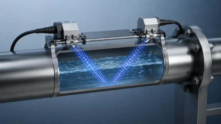
Ultrasonic sensors function similarly to radar but use high-frequency sound waves. The sensor emits an ultrasonic pulse that travels through the air gap, hits the liquid surface, and bounces back. Because the speed of sound is influenced by air temperature, these sensors usually incorporate a temperature probe to provide real-time compensation. Ultrasonic controls are highly effective for non-contact measurement in water and wastewater applications but are sensitive to heavy foam, dust, and vacuum conditions where sound cannot propagate.
Hydrostatic Level Measurement (Pressure-Based)
Hydrostatic transmitters operate on the principle that the pressure at the bottom of a liquid column is directly proportional to the height of the liquid and its density ($P = \rho gh$). By measuring this pressure, the transmitter can determine the level. For vented tanks, a gauge pressure sensor is used; for pressurized vessels, a differential pressure (DP) transmitter is required to subtract the headspace pressure from the total pressure at the bottom. This method is exceptionally reliable for deep wells and large storage tanks where non-contact sensors might struggle with range.
Magnetic Level Gauges (Buoyancy and Coupling)
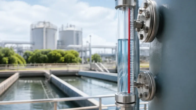
Based on Archimedes' principle and magnetic coupling, these devices consist of a bypass chamber connected to the side of a tank. Inside the chamber, a float containing a permanent magnet moves up and down with the liquid level. Outside the chamber, a series of magnetic flaps or a transmitter tracks the float's position. This provides both a local visual indication and an electrical signal for remote monitoring without the risk of glass breakage common in traditional sight glasses.
Level Switches (Point Detection)
Level switches are used to trigger alarms or control pumps at specific heights (e.g., high-level or low-level). Common technologies include vibrating forks, which detect changes in resonance frequency when immersed in liquid, and float switches, which use mechanical or reed-switch activation. These are essential for preventing tank overfills or dry-running of pumps.
Key Evaluation Criteria for Selecting Liquid Level Controls
Selecting the right liquid level control requires a systematic evaluation of the process environment. Engineers must confirm the following parameters before procurement:
1. Media Properties: The chemical compatibility of the sensor with the liquid is paramount. Consider the dielectric constant for radar, the density for hydrostatic and magnetic gauges, and the presence of corrosive agents that might require specialized coatings like PTFE.
2. Process Conditions: Operating temperatures can range from cryogenic levels to over 400°C, and pressures can vary from full vacuum to hundreds of bars. Ensure the chosen instrument is rated for the maximum possible excursions in the system.
3. Tank Geometry: The height of the tank, the presence of internal obstructions, and the nozzle diameter will dictate whether a contact or non-contact sensor is appropriate. For example, narrow tanks with internal piping may require guided wave radar rather than free-space radar.
4. Accuracy and Repeatability: While a water storage tank might only require ±10 mm accuracy, a custody transfer application in the oil industry may require precision within ±1 mm.
5. Output and Integration: Modern industrial environments often require more than a simple 4-20mA signal. Consider if the application requires HART, Modbus, or Profibus protocols for remote diagnostics and configuration.
For comprehensive technical specifications and a wider range of industrial instrumentation, engineers can visit the Main Page to review product options and application support.
Comparative Analysis of Level Measurement Technologies
The following table provides a general comparison of the most common liquid level control technologies used in industrial settings.
| Technology | Measurement Type | Recommended Media | Max Range (Typical) | Key Advantage |
| :— | :— | :— | :— | :— |
| Radar (80GHz) | Continuous (Non-contact) | Chemicals, Oils, Slurries | Up to 120 m | Unaffected by vapor/pressure |
| Ultrasonic | Continuous (Non-contact) | Water, Wastewater | 0.3 m – 30 m | Cost-effective for water |
| Hydrostatic | Continuous (Contact) | Water, Fuel, Chemicals | Up to 200 m | Ideal for deep wells/sumps |
| Magnetic Gauge | Continuous (Visual/Elec) | High Temp/High Pressure | 0.3 m – 6 m | Safe for hazardous liquids |
| Vibrating Fork | Point Level (Contact) | Most Liquids/Powders | N/A (Switch) | High reliability, no calibration |
Practical Installation Considerations and Best Practices
Even the most advanced liquid level controls will fail if installed incorrectly. Adherence to engineering best practices ensures long-term reliability.
* Dead Zones (Blocking Distance): All non-contact sensors have a "dead zone" directly beneath the sensor face where measurement is impossible. Ensure the sensor is mounted high enough so the maximum liquid level never enters this zone.
* Nozzle Design: For radar and ultrasonic sensors, the mounting nozzle should be as short and wide as possible to prevent signal interference from the nozzle walls. If a long nozzle is unavoidable, a waveguide or an extension may be necessary.
* Avoid Turbulence: Sensors should not be mounted directly over a fill pipe or near an agitator. If turbulence is unavoidable, consider using a stilling well to provide a calm surface for the measurement.
* Cable Management for Hydrostatic Sensors: When using submersible hydrostatic transmitters, the vent tube in the cable must remain unobstructed and protected from moisture. Use a desiccant cartridge or a specialized junction box to prevent water ingress into the atmospheric reference tube.
* Grounding and Shielding: To prevent electromagnetic interference (EMI) from affecting signal integrity, use shielded cables and ensure the instrument is properly grounded according to the manufacturer's specifications.
Identifying and Mitigating Risks in Level Control Systems
Implementing liquid level controls involves navigating several operational risks that can lead to false readings or equipment failure.
* Foam and Vapor: Heavy foam can absorb ultrasonic signals or cause scattering of radar waves. In such cases, 80GHz radar or hydrostatic sensors are generally preferred as they are less affected by surface conditions.
* Material Buildup: In applications involving viscous or sticky liquids, material can accumulate on the sensor face or the float. This can lead to "frozen" readings. Selecting non-contact sensors or using instruments with "self-cleaning" features or coating-resistant probes is essential.
* Density Fluctuations: Hydrostatic sensors are calibrated based on a specific liquid density. If the process involves liquids with varying densities (e.g., different grades of oil or varying salt concentrations), the level reading will drift. In these scenarios, radar is a superior choice as it is independent of density.
* Environmental Factors: Outdoor installations must account for lightning protection and extreme ambient temperatures. Sunshades and surge protectors are low-cost additions that significantly extend the lifespan of the electronics.
Frequently Asked Questions (FAQ)
Q: Can radar level meters be used in vacuum tanks?
A: Yes. Unlike ultrasonic waves, which require a medium (air) to travel, radar electromagnetic waves travel freely in a vacuum, making them ideal for vacuum distillation columns and similar vessels.
Q: What is the difference between a level transmitter and a level switch?
A: A level transmitter provides a continuous signal (e.g., 4-20mA) representing the exact level across a range (0-100%). A level switch provides a binary output (on/off) when the liquid reaches a specific point.
Q: How often should liquid level controls be calibrated?
A: Calibration frequency depends on the technology and the criticality of the process. While many modern digital sensors (like radar) exhibit very little drift, hydrostatic sensors may require annual checks to account for diaphragm fatigue or changes in media density.
Q: Are ultrasonic sensors suitable for chemical tanks?
A: It depends on the chemical. If the chemical emits heavy vapors or creates a pressurized environment, the speed of sound will change, leading to inaccuracies. For aggressive chemicals, ensure the sensor face is made of a compatible material like PVDF.
Conclusion
Effective liquid level control is a cornerstone of modern industrial engineering. By understanding the specific strengths and limitations of radar, ultrasonic, hydrostatic, and magnetic technologies, engineers can design systems that are both robust and precise. The key to success lies in matching the physical principle of the sensor to the specific challenges of the application, from the chemical properties of the media to the physical constraints of the vessel. For those seeking to implement or upgrade their current systems, reviewing the latest advancements and product configurations on the Main Page is a vital step toward achieving optimal process control.