Liquid Level Float
Liquid Level Float
In the landscape of industrial automation and process control, the liquid level float remains one of the most reliable and widely utilized technologies for monitoring fluid volumes. Despite the rise of non-contact technologies like radar and ultrasonic sensors, float-based systems offer a mechanical simplicity and physical robustness that are indispensable in specific high-pressure, high-temperature, or chemically aggressive environments. This guide examines the engineering principles, selection criteria, and operational considerations for liquid level float systems in modern industrial applications.
Principles of Buoyancy and Measurement
At the core of every liquid level float system is Archimedes' Principle. This physical law states that any object, wholly or partially immersed in a fluid, is buoyed up by a force equal to the weight of the fluid displaced by the object. For a float to function as a level indicator, it must be designed with a mean density lower than that of the process liquid.
The Buoyancy Force
In practical engineering terms, the buoyancy force ($F_b$) is calculated as:
$F_b = \rho \cdot V \cdot g$
Where:
- $\rho$ is the density of the liquid (kg/m³).
- $V$ is the volume of the displaced liquid (m³).
- $g$ is the acceleration due to gravity (approximately 9.81 m/s²).
For accurate measurement, the float must maintain a consistent "riding height" or immersion line. This is achieved by balancing the weight of the float assembly against the displacement volume. In industrial applications, the Specific Gravity (SG) of the liquid is the critical factor. If the liquid density changes due to temperature fluctuations or chemical composition shifts, the float’s position relative to the surface will change, potentially introducing measurement errors.
Signal Transduction
While the float provides the physical position, the system must translate this movement into a readable signal. This is typically achieved through three primary methods:
1. Magnetic Coupling: The float contains an internal magnet that interacts with external components (such as flags in a magnetic level gauge or reed switches in a transmitter) through a non-magnetic chamber wall.
2. Mechanical Linkage: The float is attached to a lever arm or a cable/pulley system that physically moves a pointer or rotates a potentiometer.
3. Magnetostrictive Interaction: A magnetic float moves along a sensing rod containing a waveguide. An electrical pulse sent down the waveguide interacts with the float's magnetic field, allowing for extremely high-precision continuous measurement.
Types of Liquid Level Float Systems
Selecting the correct instrument requires understanding the distinction between point-level detection and continuous level measurement.
1. Float Switches (Point Level)
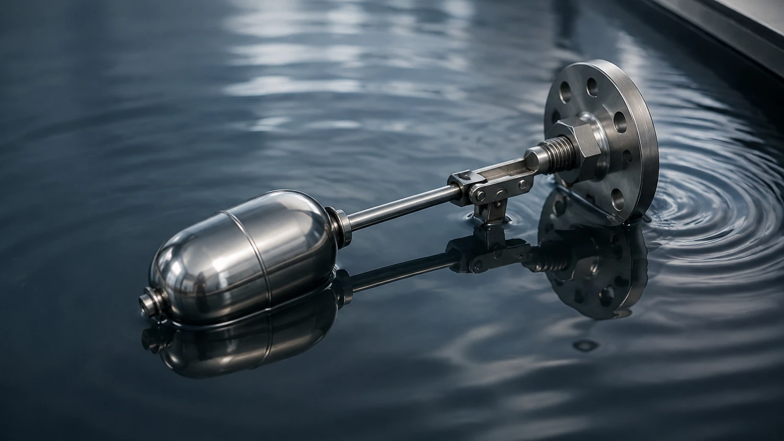
Float switches are used for discrete control, such as starting/stopping pumps or triggering high/low-level alarms. These can be small, horizontally mounted units for OEM equipment or large, cable-suspended "tilt switches" used in wastewater sumps. When the liquid reaches a predetermined level, the float tips or rises, causing a microswitch or reed switch to open or close the electrical circuit.
2. Magnetic Level Gauges (Visual Indication)
Often used as a safer alternative to glass sight gauges, the magnetic level gauge utilizes a float inside a bypass chamber. As the float rises and falls with the liquid in the main vessel, it flips magnetic rollers or flags mounted on the outside of the chamber. This provides a clear, high-visibility visual representation of the level without exposing the operator to the process fluid.
3. Continuous Float Transmitters
For applications requiring real-time data for SCADA or PLC systems, continuous transmitters are used. These typically feature a float that travels along a vertical stem. Inside the stem is a series of reed switches and resistors (forming a resistance chain) or a magnetostrictive wire. As the float moves, it changes the output signal (typically 4-20mA or a digital protocol like HART), providing a constant level reading.
Material Selection and Technical Specifications
The longevity of a liquid level float depends heavily on its material compatibility with the process medium. Factors such as corrosion, pressure, and temperature must be evaluated during the design phase.
Common Float Materials
| Material | Temperature Range | Pressure Rating | Typical Applications |
| :— | :— | :— | :— |
| 316L Stainless Steel | -196°C to +400°C | Up to 200 bar | Oil & gas, high-pressure steam, food & beverage. |
| Titanium | -50°C to +450°C | High Pressure | Extremely low-density liquids, aggressive acids. |
| Polypropylene (PP) | -10°C to +80°C | Low (PN10) | Water treatment, mild acids, plating baths. |
| PVDF / PTFE | -30°C to +150°C | Moderate | Concentrated acids, high-purity chemicals. |
| Buna-N (Nitril) | -20°C to +100°C | Low | Hydraulic oils, fuels, diesel storage. |
Density Considerations
Standard floats are usually designed for liquids with an SG of 0.8 to 1.2. However, in the petrochemical industry, liquids like LPG (Liquefied Petroleum Gas) may have an SG as low as 0.45. In such cases, the float must be engineered with a larger volume and thinner walls (often using titanium) to ensure it remains buoyant while withstanding the external tank pressure.
Installation Considerations
Proper installation is vital to prevent mechanical failure and ensure accuracy. Engineers should adhere to the following guidelines:
* Vertical Alignment: For vertical stem transmitters and magnetic level gauges, the instrument must be mounted perfectly plumb. Even a slight tilt can cause the float to bind against the chamber or stem, leading to "stuck" readings.
* Turbulence and Agitation: In tanks with mixers or high-velocity inflow, the float can be tossed around, leading to mechanical fatigue or erratic signals. In these environments, a stilling well (a perforated pipe that surrounds the float) should be installed to provide a calm surface for measurement.
* Magnetic Interference: Since many float systems rely on magnetic coupling, they should be kept away from large motors, high-voltage cables, or other sources of strong electromagnetic fields that could interfere with the magnetic interaction between the float and the sensor.
* Clearance: Ensure there is sufficient overhead clearance to remove the float and stem for maintenance. If headspace is limited, flexible magnetic probes or side-mounted horizontal switches may be more appropriate.
Limitations and Risks
While highly reliable, liquid level float technology is not a universal solution. Understanding its limitations prevents costly misapplications.
1. Build-up and Scaling: In liquids that are prone to crystallization, coating, or heavy scaling (such as lime slurry or crude oil with high paraffin content), the float can become coated. This increases its weight (changing the immersion level) or causes it to seize entirely. In these cases, non-contact radar is often preferred.
2. Mechanical Wear: Because it is a moving part, the float and its guides are subject to wear over time, especially in applications with frequent level cycles.
3. Specific Gravity Sensitivity: If the process involves mixing different fluids where the total density varies significantly, the float's accuracy will drift. For example, a float calibrated for water (SG 1.0) will read lower in a mixture of water and ethanol (SG ~0.85).
4. Shock and Vibration: High-frequency vibration can damage reed switch chains or cause magnetic flags to flip unintentionally.
Engineering FAQ
Q: Can a liquid level float be used for interface measurement?
A: Yes. By weighting the float so that its density is between the densities of two immiscible liquids (e.g., oil and water), the float will sink through the upper layer and float on the lower layer, effectively tracking the interface level.
Q: What is the minimum density a float can measure?
A: With specialized materials like titanium and high-volume spherical designs, floats can be manufactured to track liquids with a specific gravity as low as 0.38, though 0.5 is a more common practical limit for standard industrial hardware.
Q: How do I handle pressurized tanks?
A: The float must be rated for the maximum design pressure of the vessel. In high-pressure applications, the float is often a sealed, pressurized sphere or a solid-core design to prevent collapse. The chamber of a magnetic level gauge must also be rated to the same pressure standards as the tank itself.
Selecting the Right Solution
When designing a level control system, it is essential to partner with a manufacturer that understands the nuances of material science and fluid dynamics. For a comprehensive overview of available technologies, including radar, ultrasonic, and hydrostatic options alongside traditional float systems, engineers should consult the Main Page of professional instrumentation providers. Comparing these technologies side-by-side allows for a more informed decision based on the specific constraints of the facility.
In summary, the liquid level float remains a cornerstone of industrial instrumentation. By carefully matching the float material and design to the liquid's specific gravity and chemical properties, and by ensuring a stable installation environment, operators can achieve years of maintenance-free, accurate level monitoring. Whether used as a simple high-level alarm or a high-precision magnetostrictive transmitter, the float provides a physical certainty that electronic-only sensors sometimes struggle to match in the harshest industrial conditions.