Liquid Level Sensors
Liquid Level Sensors
In the landscape of industrial automation, the accurate monitoring of fluids is a fundamental requirement for process safety, inventory management, and operational efficiency. Liquid level sensors encompass a broad range of technologies designed to detect the height of a liquid within a vessel, tank, or open channel. Whether managing corrosive chemicals, potable water, or volatile hydrocarbons, selecting the appropriate sensing technology requires a deep understanding of the physical principles at play and the environmental constraints of the application.
For engineers and procurement specialists, the challenge lies in navigating the trade-offs between accuracy, maintenance requirements, and total cost of ownership. This guide provides a technical overview of the primary liquid level measurement technologies, offering a practical reference for selecting and implementing these instruments in industrial environments. For those seeking specific hardware specifications, you may Review product options and application support on our Main Page.
Understanding Liquid Level Measurement Principles
Before selecting a device, it is essential to categorize liquid level sensors by their operating principle. These are generally divided into non-contact and contact-based methods.
1. Radar Level Measurement (Non-Contact)
Radar sensors utilize electromagnetic waves, typically in the microwave spectrum (6GHz to 80GHz), to measure distance.
* Principle: The sensor emits a high-frequency signal that travels to the liquid surface and reflects back. By measuring the Time-of-Flight (ToF) or using Frequency Modulated Continuous Wave (FMCW) technology, the device calculates the distance based on the speed of light.
* Advantages: Radar is unaffected by changes in temperature, pressure, or the presence of dust and vapors. High-frequency 80GHz radar offers a narrow beam angle, which is ideal for tanks with internal obstructions.
* Limitations: The effectiveness depends on the dielectric constant ($ε_r$) of the liquid. Low dielectric fluids (like certain oils) reflect less energy, requiring more sensitive electronics or guided wave variants.
2. Ultrasonic Level Measurement (Non-Contact)
Ultrasonic sensors use sound waves to determine the level of the medium.
* Principle: The transducer emits an ultrasonic pulse (typically 20kHz to 200kHz) which reflects off the liquid surface. The time elapsed between emission and reception is proportional to the distance.
* Advantages: Cost-effective and easy to install for standard water and wastewater applications.
* Limitations: Because sound requires a medium to travel, ultrasonic sensors cannot work in a vacuum. They are also sensitive to air temperature fluctuations (requiring compensation), heavy foam, and surface turbulence, which can scatter the sound waves.
3. Hydrostatic Level Measurement (Contact)
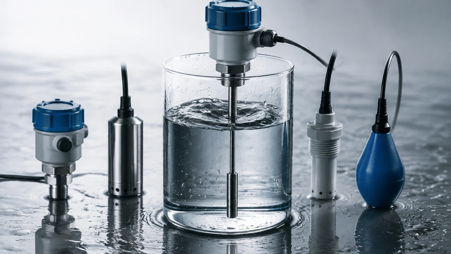
Hydrostatic sensors are pressure-based instruments that reside at the bottom of a tank or are submerged in the liquid.
* Principle: The sensor measures the pressure exerted by the liquid column above it. The relationship is defined by the formula: $P = ρ × g × h$, where $P$ is pressure, $ρ$ is the density of the liquid, $g$ is gravity, and $h$ is the height of the liquid.
* Advantages: Highly reliable for vented tanks and deep wells. They are relatively immune to surface foam or turbulence.
* Limitations: Changes in liquid density (due to temperature or concentration changes) will introduce errors unless the system is calibrated for density compensation.
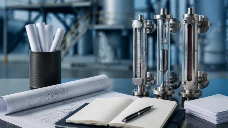
4. Magnetic Level Gauges (Contact/Visual)
Magnetic gauges provide both a local visual indication and, often, a remote electronic signal.
* Principle: A float containing a permanent magnet moves with the liquid level inside a bypass chamber. This magnet flips external rollers or flags to show the level visually and can trigger reed switches or a magnetostrictive transmitter for remote monitoring.
* Advantages: No power is required for visual indication, and they are excellent for high-pressure, high-temperature, or hazardous applications where glass gauges are unsafe.
* Limitations: Limited to liquids that do not cause build-up or scaling on the float, which could lead to mechanical sticking.
Comparative Analysis of Sensor Technologies
Choosing between different liquid level sensors involves weighing the physical characteristics of the process against the required precision. The following table summarizes the performance of common technologies.
| Technology | Typical Accuracy | Operating Range | Best Suited For | Main Limitation |
| :— | :— | :— | :— | :— |
| 80GHz Radar | ±1 mm | Up to 120 m | Chemical tanks, solids, precise inventory | High initial cost |
| Ultrasonic | ±0.25% of range | 0.25 m – 15 m | Water treatment, open channels | Affected by foam/vapor |
| Hydrostatic | ±0.1% to ±0.5% | 1 m – 200 m | Deep wells, vented reservoirs | Density dependent |
| Magnetic Gauge | ±5 mm | 0.3 m – 6 m | Boilers, oil/gas separators | Mechanical float fouling |
| Level Switch | Point detection | N/A | Overfill protection, pump control | No continuous output |
Key Selection Criteria for Industrial Applications
When specifying liquid level sensors, engineers must confirm several technical parameters to ensure long-term reliability.
Media Characteristics
* Corrosivity: For aggressive acids or bases, non-contact sensors (Radar/Ultrasonic) with PTFE or PVDF wetted parts are preferred to prevent material degradation.
* Viscosity and Coating: Highly viscous liquids or those that crystallize can coat contact-based probes. In these instances, non-contact radar is the superior choice.
* Dielectric Constant: For radar applications, the $ε_r$ value must be known. If the value is below 1.5, a guided wave radar or a different technology may be necessary.
Vessel Geometry and Environment
* Dead Zones: Every sensor has a "blocking distance" or dead zone near the sensor face where measurement is impossible. For short tanks, a sensor with a small dead zone is critical.
* Internal Obstructions: Agitators, ladders, and heating coils can create false echoes for radar and ultrasonic sensors. Modern instruments use "false echo suppression" software to ignore these fixed objects.
* Pressure and Temperature: Ensure the sensor housing and process connection can withstand the maximum possible pressure (measured in bar or PSI) and temperature (°C).
Installation Best Practices and Engineering Considerations
Correct installation is as vital as selecting the right sensor. Even the most advanced liquid level sensors will fail if poorly positioned.
1. Avoid the Inlet: Never install a sensor directly above the liquid fill stream. The turbulence and the falling liquid will cause erratic readings or signal loss.
2. Beam Angle Awareness: For radar and ultrasonic devices, ensure the signal beam does not hit the tank wall. If the beam hits a weld or a wall, it will return a false signal.
3. Stilling Wells: In tanks with heavy agitation or foam, installing the sensor inside a stilling well (a vertical pipe) can provide a calm surface for more accurate measurement.
4. Submersible Venting: For hydrostatic sensors, the capillary tube in the cable must be vented to the atmosphere to compensate for changes in barometric pressure. Ensure the vent filter is kept dry and clear.
5. Mounting Orientation: Ensure the sensor is mounted perfectly vertical. A tilt of even a few degrees can significantly reduce the signal strength returned to the transducer.
Managing Common Risks and Operational Limitations
While modern liquid level sensors are robust, certain environmental factors present ongoing risks to measurement integrity.
* Foam Interference: Heavy, dense foam can absorb ultrasonic and radar signals. If foam is a constant factor, hydrostatic sensors or specialized low-frequency radar may be required.
* Condensation and Buildup: In high-humidity applications, condensation can form on the sensor face. Some radar sensors feature a convex lens design to allow droplets to run off, preventing signal attenuation.
* Ambient Noise: In ultrasonic applications, high-frequency noise from pneumatic equipment can interfere with the sensor. Proper shielding and frequency selection can mitigate this.
* Power Supply Stability: Industrial sensors typically operate on 24V DC. Fluctuations in power can lead to intermittent signal loss or calibration drift. Utilizing a stabilized power source and shielded cabling is recommended.
Frequently Asked Questions (FAQ)
Q: Can I use one sensor for multiple different liquids?
A: If using a non-contact radar, yes, provided the dielectric constants are similar. If using hydrostatic sensors, you must recalibrate the device if the liquid density changes significantly.
Q: What is the difference between a level sensor and a level switch?
A: A level sensor provides continuous measurement (e.g., 0-100% full), typically outputting a 4-20mA or digital signal. A level switch is a point-level device that only detects if the liquid has reached a specific height (e.g., high-level alarm).
Q: How often do liquid level sensors need calibration?
A: This depends on the technology. Radar and ultrasonic sensors are generally "drift-free" and require infrequent calibration. Hydrostatic and mechanical sensors should be checked annually to account for diaphragm fatigue or mechanical wear.
Q: Is 80GHz radar always better than 26GHz?
A: Not necessarily. While 80GHz offers a narrower beam and better resolution, 26GHz radar can be more effective in extremely dusty environments or where the signal needs to penetrate light foam.
Conclusion
The selection of liquid level sensors is a critical decision that impacts the safety and profitability of industrial operations. By understanding the underlying physics of radar, ultrasonic, and hydrostatic measurement, and by accounting for the specific constraints of the installation site, engineers can implement solutions that provide years of reliable service. For a comprehensive look at available measurement hardware and technical support, visit the Main Page to Review product options and application support.