Low Flow Flow Switch
Low Flow Flow Switch
In industrial process control, monitoring the presence or absence of fluid movement is a fundamental safety and operational requirement. While high-volume flow monitoring is common, the ability to detect extremely small movements of liquid or gas—often referred to as low flow conditions—is critical for protecting sensitive equipment, ensuring proper lubrication, and managing precise chemical dosing. A low flow flow switch is a specialized instrument designed to trigger an electrical signal when the flow rate drops below or rises above a specific, often minute, threshold.
For engineers and plant managers, selecting the right low flow flow switch requires an understanding of different sensing technologies, as the physics of fluid dynamics changes significantly at lower velocities. This guide explores the principles, selection criteria, and installation best practices for these essential industrial components.
Measurement Principles for Low Flow Detection
Detecting low flow rates requires higher sensitivity than standard flow switches. Traditional paddle switches often lack the surface area or mechanical leverage to respond to slow-moving fluids. Consequently, low flow applications typically utilize thermal dispersion or high-precision mechanical designs.
Thermal Dispersion (Calorimetric) Principle
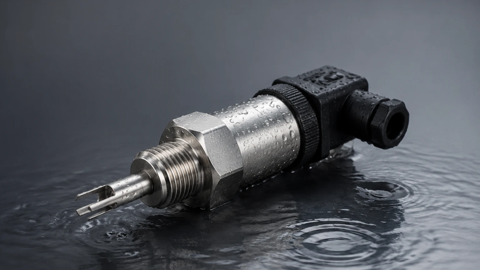
Thermal dispersion switches are among the most common solutions for low flow detection due to their lack of moving parts and high sensitivity. The sensor probe typically contains two thermistors: one is heated, and the other measures the ambient temperature of the fluid.
When the fluid is stationary, the temperature difference between the two sensors is at its maximum. As fluid begins to move, it carries heat away from the heated sensor (the cooling effect). The rate of heat loss is proportional to the flow velocity. The switch electronics monitor this "Delta T" and trigger the output when it reaches a predetermined set point. This technology is exceptionally effective for detecting flows as low as 0.01 meters per second (m/s).
Variable Area (Piston and Spring) Principle
For liquid applications where a mechanical action is preferred, a piston-style variable area switch is often used. In this design, a calibrated piston is housed within the flow path. As fluid enters the switch, it pushes against the piston, which is held in place by a precision spring.
At a specific flow rate, the pressure of the fluid overcomes the spring force, moving the piston. The piston usually contains a permanent magnet that actuates a reed switch located outside the fluid path. Because the internal tolerances are tight and the spring can be finely tuned, these switches can detect flow rates as low as 0.1 liters per minute (L/min) or approximately 0.026 gallons per minute (GPM).
Ultrasonic Sensing
In high-purity or highly corrosive environments, non-invasive ultrasonic flow switches may be employed. These use the Doppler effect or transit-time differences to detect movement. While often more expensive, they offer the advantage of zero pressure drop and no contact with the media, which is vital in pharmaceutical or semiconductor manufacturing where even low flow must be monitored without contamination risks.
Key Evaluation Criteria for Selection
Choosing a low flow flow switch involves more than just matching pipe sizes. Because low flow states are often near the "noise" threshold of a system, the following criteria must be evaluated to ensure reliability.
1. Minimum Set Point and Hysteresis
The most critical factor is the minimum flow rate the switch can reliably detect. It is essential to distinguish between the "set point" (where the switch triggers) and the "reset point" (where it returns to its original state). This difference, known as hysteresis, prevents the switch from "chattering" or rapidly cycling if the flow rate fluctuates slightly around the set point.
2. Fluid Properties: Viscosity and Conductivity
Mechanical switches are highly sensitive to changes in fluid viscosity. If a lubricant thickens due to temperature drops, a piston-style switch may require more force to move, leading to false low-flow alarms. Conversely, thermal dispersion switches are affected by the thermal conductivity of the fluid. A switch calibrated for water will not function correctly in oil without recalibration, as oil carries heat away at a different rate.
3. Operating Environment (Pressure and Temperature)
Low flow systems often operate under high pressure (e.g., hydraulic lines) or extreme temperatures (e.g., coolant loops for furnaces). Ensure the switch body and seals (O-rings) are rated for the maximum system pressure and temperature. For hazardous areas, such as chemical processing plants, explosion-proof or intrinsically safe certifications are mandatory.
4. Material Compatibility
The wetted materials—those in direct contact with the fluid—must be chemically compatible. Stainless steel (316L) is the standard for many industrial applications, but aggressive chemicals may require Hastelloy, Monel, or plastic bodies like PVC or PTFE. For more information on instrument compatibility and specialized industrial solutions, you can Review product options and application support to match materials to your specific media.
Practical Selection Table
| Technology | Typical Min. Flow (Liquid) | Media Type | Pros | Cons |
| :— | :— | :— | :— | :— |
| Thermal Dispersion | 0.01 m/s | Liquids & Gases | No moving parts; very sensitive; low pressure drop. | Slow response time; sensitive to media changes. |
| Piston/Spring | 0.1 L/min | Clean Liquids | Fast response; economical; orientation independent. | Moving parts can wear; sensitive to debris. |
| Ultrasonic | 0.05 m/s | Conductive/Non-conductive | Non-invasive; zero pressure drop. | Higher cost; requires specific pipe conditions. |
| Micro-Vane | 0.5 L/min | Low-viscosity Liquids | Simple mechanical visual. | Not suitable for high-viscosity or dirty fluids. |
Installation Considerations
A low flow flow switch is only as accurate as its installation. Because low flow velocities are easily disturbed by turbulence, following engineering best practices is vital.
* Straight Pipe Runs: To ensure a stable flow profile, install the switch in a straight section of pipe. A general rule is to have at least 5 diameters (5D) of straight pipe upstream and 3 diameters (3D) downstream of the switch. For extremely low flow rates, increasing the upstream run to 10D may be necessary to eliminate turbulence from elbows or valves.
* Orientation: Some mechanical low flow switches are gravity-dependent. While spring-loaded piston models can often be mounted in any orientation, they perform most consistently when mounted vertically with the flow moving upward. This ensures the pipe remains full of liquid and helps prevent air pockets.
* Air Pockets and Bubbles: In low flow liquid systems, air bubbles can become trapped or move slowly through the sensor. In a thermal switch, an air bubble passing the probe may be interpreted as a sudden drop in flow (as air dissipates heat differently than liquid), causing a false alarm. Always install switches at a low point in the piping or in a vertical rise to ensure the sensor remains fully submerged.
* Filtration: For mechanical low flow switches, even small particles can jam the piston or vane. Installing a Y-strainer upstream of the switch is highly recommended to protect the internal mechanism.
Limitations and Common Risks
While low flow flow switches are robust, they are subject to specific industrial risks that can lead to failure or inaccuracy.
1. Scaling and Coating: In water treatment or chemical dosing, minerals or polymers can build up on the sensor probe (thermal) or the piston (mechanical). A coating on a thermal probe acts as an insulator, significantly slowing response time or causing the switch to fail to detect flow changes entirely.
2. Viscosity Shifts: As mentioned, mechanical switches are calibrated for a specific viscosity. If the process fluid temperature varies significantly, the resulting change in viscosity will shift the flow set point. In such cases, a temperature-compensated thermal switch or an ultrasonic switch is a better choice.
3. False Triggers from Vibration: In high-vibration environments (near large pumps or compressors), mechanical reed switches within a flow switch can be vibrated into a closed or open state erroneously. Using solid-state outputs or ensuring the switch is dampened can mitigate this risk.
Frequently Asked Questions (FAQs)
Q: Can a low flow flow switch be used for both liquids and gases?
A: Some technologies, like thermal dispersion, are versatile enough for both. However, the calibration is vastly different because the heat transfer properties of air are much lower than those of water. Always specify the media during the procurement process.
Q: What is the typical response time?
A: Mechanical switches (piston/vane) respond almost instantaneously (milliseconds). Thermal dispersion switches have a thermal lag, typically responding within 1 to 10 seconds depending on the flow change and the media.
Q: How do I calibrate the set point?
A: Most industrial low flow switches feature an adjustment screw or a digital interface. Calibration should be performed under actual operating conditions—ideally by establishing the minimum safe flow in the system and adjusting the switch until it just triggers.
Q: Is there a pressure drop associated with these switches?
A: Yes, mechanical switches create a slight pressure drop because the fluid must physically move a component. Thermal dispersion and ultrasonic switches offer negligible to zero pressure drop, which is advantageous in gravity-fed or low-pressure systems.
Conclusion
Implementing a low flow flow switch is a critical step in safeguarding industrial machinery and maintaining process integrity. Whether protecting a high-pressure pump from running dry or ensuring that a cooling loop is active for a sensitive laser, the right switch provides the first line of defense against system failure. By understanding the underlying measurement principles—whether the heat-transfer sensitivity of thermal dispersion or the mechanical reliability of a piston-spring assembly—engineers can select a solution that balances accuracy, durability, and cost.
When specifying these instruments, always consider the specific nuances of your fluid, including its viscosity, potential for debris, and the required response time. For those seeking technical specifications or customized OEM/ODM solutions for flow and level measurement, visiting professional resources like the Welk Main Page can provide the necessary data to finalize a project design and ensure long-term operational success.