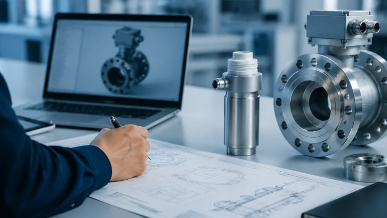
Lr2050
Lr2050
In the landscape of industrial automation and process control, the demand for precise, non-contact level measurement has led to the widespread adoption of high-frequency radar technology. The lr2050 represents a specific class of radar level transmitters designed to bridge the gap between high-performance requirements and cost-effective deployment. As industries move away from mechanical or contact-based measurement systems—which are prone to wear and chemical attack—the lr2050 offers a robust alternative that utilizes electromagnetic waves to determine the distance to a product surface with millimeter precision.
This guide provides a comprehensive technical overview of the lr2050, exploring its underlying physics, typical specifications, and the practical engineering considerations required for successful integration into industrial environments. For those seeking a broader range of instrumentation, visiting the Main Page of a specialized manufacturer provides further insight into how radar technology fits within a complete measurement portfolio.
Measurement Principles of Radar Technology
The lr2050 operates on the principle of radar (Radio Detection and Ranging). Specifically, most instruments in this category utilize either Pulse Radar or Frequency Modulated Continuous Wave (FMCW) technology. Understanding these principles is essential for selecting the right sensor for a specific application.
Time of Flight (ToF)
In pulse-based radar systems, the lr2050 emits short microwave pulses toward the medium. These pulses travel at the speed of light, reflect off the surface of the material, and return to the sensor's antenna. The instrument measures the "Time of Flight"—the duration between emission and reception. Since the speed of light is constant, the distance (D) is calculated using the formula:
D = (c × t) / 2
Where *c* is the speed of light and *t* is the measured time. The level of the tank is then derived by subtracting this distance from the total height of the vessel.
Frequency and Beam Angle
The lr2050 typically operates in the K-band (approximately 26 GHz). High-frequency radar offers a significant advantage over lower-frequency models (such as 6 GHz C-band radar): a narrower beam angle. A narrower beam allows the signal to avoid internal tank obstructions like agitators, heating coils, or ladders, which would otherwise cause false reflections. This makes the lr2050 particularly suitable for tall, narrow silos or tanks with complex internal geometries.
Technical Specifications and Performance
When evaluating the lr2050 for a project, engineers must consider the physical and electrical limits of the device. Below are the standard specifications typically associated with this class of high-frequency radar transmitter.
| Feature | Specification (Typical) |
| :— | :— |
| Measuring Range | Up to 30 meters (liquids) / 15 meters (solids) |
| Accuracy | ±3 mm to ±5 mm |
| Frequency | 26 GHz |
| Process Temperature | -40°C to +150°C (standard); up to +250°C with cooling |
| Process Pressure | -1 bar to 40 bar (4.0 MPa) |
| Output Signal | 4-20mA HART, RS485 Modbus, or Profibus |
| Housing Material | Aluminum or Stainless Steel (316L) |
| Antenna Type | Horn antenna or sealed teardrop (PTFE/PVDF) |
These specifications ensure that the lr2050 can handle the rigors of chemical processing, water treatment, and bulk solids storage. The choice of antenna material is particularly important; for example, a PTFE-coated antenna is required when measuring aggressive acids to prevent corrosion of the sensor head.
Comparison with Alternative Technologies
To understand why an engineer might choose the lr2050, it is helpful to compare it against other common level measurement technologies such as ultrasonic sensors and hydrostatic transmitters.
Radar vs. Ultrasonic
Ultrasonic sensors use sound waves, which require a medium (air) to travel. Changes in air temperature, pressure, or the presence of heavy steam and dust can significantly alter the speed of sound, leading to measurement errors. The lr2050, using electromagnetic waves, is unaffected by vacuum, high pressure, or gas composition in the headspace. This makes radar the preferred choice for volatile liquids or high-temperature steam applications.
Radar vs. Hydrostatic
Hydrostatic transmitters measure the pressure exerted by a liquid column. While accurate, they are contact-based and depend on the density of the liquid. If the density changes (due to temperature fluctuations or mixing of different products), the level reading will drift. The lr2050 is a top-down, non-contact measurement that is independent of product density, making it more versatile for multi-product tanks.
Industrial Applications for the lr2050
The versatility of the lr2050 allows it to be deployed across various sectors where reliability is non-negotiable.
1. Water and Wastewater Treatment
In wastewater applications, sensors are often exposed to hydrogen sulfide gas and high humidity. The non-contact nature of the lr2050 prevents sensor fouling. It is commonly used in lift stations, open channels, and chemical storage tanks for alum or lime slurry.
2. Chemical and Petrochemical
The ability to measure through plastic tank walls or withstand high-pressure metallic vessels makes the lr2050 ideal for aggressive chemicals. Its high frequency allows it to focus on the liquid surface even when there is moderate surface turbulence or agitation.
3. Food and Beverage
With stainless steel housings and hygienic process connections (such as Tri-Clamp), the lr2050 meets the sanitary requirements of the food industry. It can monitor the level of milk, oils, or syrups without the risk of contamination associated with submerged probes.
4. Bulk Solids
While radar is often associated with liquids, the lr2050 is effective for measuring small-grain solids or powders in silos. The 26 GHz signal can penetrate dust clouds that would typically blind an ultrasonic sensor.
Installation Considerations and Best Practices
Correct installation is the most critical factor in ensuring the long-term accuracy of the lr2050. Even the most advanced radar can fail if poorly positioned.
1. Nozzle Height and Diameter: The antenna should ideally extend slightly past the bottom of the mounting nozzle. If the nozzle is too long or narrow, the radar signal may reflect off the nozzle walls, creating a "ringing" effect that masks the true level signal.
2. Beam Path Clearance: The "keep-out zone" of the radar beam is a cone-shaped area. Engineers must ensure no pipes, ladders, or agitator blades enter this cone. If obstructions are unavoidable, most lr2050 units include a "false echo suppression" feature, allowing the software to ignore fixed reflections.
3. Avoid Central Mounting: In tanks with a domed top, the sensor should not be mounted in the exact center. Domed roofs can act as a parabolic reflector, concentrating unwanted signals back at the sensor. Mounting the lr2050 at 1/2 to 1/3 of the tank radius is generally recommended.
4. Inlet Interference: The sensor should never be mounted directly above the product inlet. The falling stream of liquid or solids will reflect the radar signal, causing the sensor to report a full tank regardless of the actual level.

Limitations and Environmental Factors
While the lr2050 is a highly capable instrument, it is not a universal solution. Certain physical properties of the medium can impact performance.
* Dielectric Constant (εr): Radar relies on a change in the dielectric constant at the air-product interface. Liquids with a very low dielectric constant (such as pure oils or liquefied gases) reflect less energy. In these cases, a guided wave radar or a larger horn antenna may be required to amplify the return signal.
* Heavy Foam: Dense, thick foam can absorb radar signals rather than reflecting them. If the foam is light and airy, the radar may see through it to the liquid; if it is conductive and dense, the radar might reflect off the top of the foam. Testing is often required for high-foam applications.
* Extreme Turbulence: While the lr2050 handles moderate agitation well, extreme turbulence can scatter the radar signal. Using a stilling well (a bypass pipe) can provide a calm surface for the radar to measure if the process allows for it.
Maintenance and Troubleshooting
One of the primary B2B benefits of the lr2050 is its low maintenance requirement. Since there are no moving parts and no contact with the medium, mechanical wear is non-existent. However, periodic checks are recommended:
* Antenna Cleaning: In applications with heavy condensation or crystallization, material may build up on the antenna face. While many radar units can "see through" a thin layer of buildup, heavy coating will eventually attenuate the signal.
* Signal Strength Monitoring: Most modern lr2050 transmitters provide a signal-to-noise ratio or echo amplitude value. Monitoring this via HART or Modbus allows maintenance teams to predict when cleaning is required before a failure occurs.
Frequently Asked Questions (FAQ)
Q: Can the lr2050 measure through a plastic tank lid?
A: Yes. Since plastic is non-conductive and has a low dielectric constant, radar signals can pass through it. This allows for "tank-side" measurement without ever cutting a hole in the vessel, which is ideal for IBC totes or chemical storage.
Q: What is the minimum distance the lr2050 can measure?
A: This is known as the "dead zone" or blocking distance. For the lr2050, it is typically between 0.2 meters and 0.4 meters from the antenna tip. Measurements within this range are not reliable.
Q: Is the lr2050 suitable for explosive atmospheres?
A: Most versions of the lr2050 are available with ATEX, IECEx, or FM certifications for use in Zone 0, 1, or 2 hazardous areas, provided they are installed with appropriate safety barriers.
Conclusion
The lr2050 is a cornerstone of modern industrial level measurement, offering a balance of precision, durability, and ease of use. By understanding the electromagnetic principles and following strict installation guidelines, process engineers can achieve reliable data even in the most challenging environments. For detailed product selection and to explore customized OEM/ODM options, professionals are encouraged to consult the Main Page of their equipment provider to ensure the selected instrument matches the specific chemical and physical demands of their facility.