Mechanical Flow Sensor
Mechanical Flow Sensor
In the landscape of industrial process control, the mechanical flow sensor remains a foundational technology for monitoring fluid movement. Despite the rise of solid-state and digital measurement technologies, mechanical sensors are valued for their reliability, direct physical interaction with the process media, and often, their ability to operate without external power. For engineers and facility managers, understanding the mechanics, selection criteria, and installation requirements of these devices is essential for maintaining accurate system telemetry.
While often categorized separately from level measurement, flow and level are intrinsically linked in industrial automation. Precise flow data allows for the calculation of volume changes in tanks, providing a redundant check against level transmitters. This article explores the technical principles of mechanical flow sensors, their various configurations, and how they integrate into broader process monitoring strategies.
Understanding the Principles of Mechanical Flow Measurement
Mechanical flow sensors operate on the principle of converting the kinetic energy of a moving fluid into mechanical motion. This motion is then quantified to determine the flow rate. Unlike non-intrusive methods, mechanical sensors feature moving parts that reside directly in the flow stream.
Kinetic Energy Conversion
Most mechanical sensors utilize a rotor, impeller, or piston. As the fluid (liquid or gas) passes through the sensor body, it exerts force on these components. The speed of rotation or the frequency of displacement is directly proportional to the velocity of the fluid. In modern systems, this mechanical movement is typically captured by a magnetic pick-up or a Hall-effect sensor, which converts the physical rotation into an electrical pulse or a 4-20mA signal.
Displacement Principles
Positive displacement (PD) sensors work differently by capturing a specific, fixed volume of fluid and moving it through the meter. By counting how many times these discrete volumes are "discharged," the sensor provides highly accurate volumetric flow data. This is particularly effective for high-viscosity fluids where kinetic energy conversion might be inconsistent.
Primary Types of Mechanical Flow Sensors
Selecting the correct sensor requires an understanding of the specific mechanical design and its suitability for different media and flow profiles.
1. Turbine Flow Meters
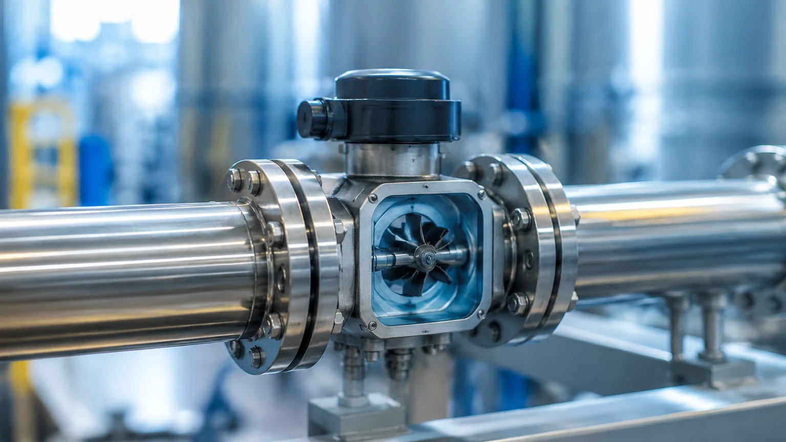
Turbine meters consist of a multi-bladed rotor suspended in the fluid stream. As the fluid moves, the rotor spins at a speed proportional to the flow velocity. These are highly accurate for clean, low-viscosity liquids and gases.
* Best for: Water, light oils, and liquified gases.
* Limitation: Susceptible to damage from debris and high-viscosity fluids that create drag on the blades.
2. Paddle Wheel Sensors
Often used in water treatment and irrigation, paddle wheel sensors feature a rotor oriented perpendicular to the flow. Only a portion of the blades is inserted into the flow stream. They are cost-effective and easy to maintain.
* Best for: Large pipe diameters and general water monitoring.
* Limitation: Lower accuracy compared to turbine or PD meters.
3. Oval Gear Meters
This is a type of positive displacement meter featuring two interlocking oval-shaped gears. The fluid forces the gears to rotate, and each rotation traps a specific volume of fluid. Because the measurement is volumetric, changes in viscosity have minimal impact on accuracy.
* Best for: Oils, fuels, and chemical additives.
* Limitation: Significant pressure drop across the sensor.
4. Variable Area Meters (Rotameters)
These consist of a tapered tube and a float. The fluid pushes the float upward until the upward force equals the weight of the float. The position of the float indicates the flow rate on a scale. While traditionally purely mechanical/visual, many now include electronic transmitters.
* Best for: Localized visual indication and low-flow gas applications.
* Limitation: Must be mounted vertically; lower precision.
Selection Criteria for Industrial Applications
Choosing a mechanical flow sensor involves balancing technical requirements with cost and maintenance capabilities. The following table provides a comparison of key performance metrics.
| Sensor Type | Typical Accuracy | Viscosity Handling | Pressure Drop | Maintenance Level |
| :— | :— | :— | :— | :— |
| Turbine | ±0.25% to ±1% | Low | Medium | Moderate |
| Paddle Wheel | ±1% to ±5% | Low | Low | Low |
| Oval Gear | ±0.5% | High | High | Moderate |
| Rotameter | ±2% to ±10% | Low to Medium | Low | Low |
| Nutating Disc | ±1% to ±2% | Medium | Medium | Moderate |
Media Characteristics
The first step in selection is defining the fluid. Is it corrosive? Does it contain solids? Mechanical sensors with internal bearings (like turbines) will fail quickly if the fluid is abrasive. For high-viscosity fluids like heavy oils, a positive displacement meter is usually the only viable mechanical option.
Flow Range and Turn-down Ratio
Every sensor has a minimum and maximum flow rate (the turn-down ratio). If the flow rate drops below the minimum, the mechanical friction of the sensor components will exceed the kinetic energy of the fluid, resulting in zero or highly inaccurate readings.
Installation Guidelines and Best Practices
Mechanical flow sensors are sensitive to the flow profile. Turbulence caused by elbows, valves, or pumps can lead to significant measurement errors.
Straight Pipe Requirements
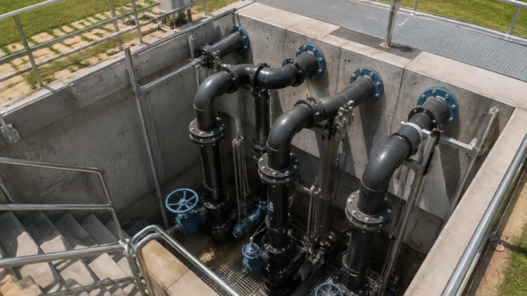
To ensure a laminar flow profile, most mechanical sensors require a specific length of straight pipe upstream and downstream. A common engineering rule is "10D upstream and 5D downstream," meaning the straight pipe should be 10 times the pipe diameter before the sensor and 5 times the diameter after it.
Orientation and Gravity
Orientation is critical. For example, a rotameter must be perfectly vertical to function. Turbine and paddle wheel sensors can often be mounted horizontally, but the pipe must remain full of liquid. If the pipe is only partially full, the sensor will read the velocity of the surface or air, leading to massive errors. In such cases, integrating data from the Main Page of an instrumentation provider to cross-reference with level sensors can help identify empty-pipe conditions.
Filtration
Because mechanical flow sensors have moving parts with tight tolerances, upstream filtration is often mandatory. A Y-strainer or basket filter should be installed to prevent debris from jamming rotors or damaging gear teeth. The mesh size of the filter should be selected based on the sensor manufacturer's specifications, typically ranging from 40 to 100 mesh.
Limitations and Common Operational Risks
While robust, mechanical flow sensors have inherent limitations that must be managed through proactive maintenance and system design.
1. Mechanical Wear: Moving parts eventually wear out. Bearings in turbine meters and the teeth in gear meters will degrade over time, leading to a "drift" in calibration. Regular recalibration against a master meter is necessary.
2. Pressure Loss: Every mechanical sensor introduces an obstruction in the line. This results in a pressure drop (Delta P). In low-pressure systems, the pressure drop across an oval gear meter might be high enough to significantly reduce the flow rate of the process.
3. Sensitivity to Entrained Air: Mechanical meters cannot distinguish between liquid and gas. If air bubbles are trapped in a liquid line, the sensor will spin faster, over-reporting the volume of liquid delivered.
4. Fluid Compatibility: The materials of the rotor and seals must be compatible with the process fluid. For example, stainless steel rotors are required for corrosive chemicals, while food-grade plastics may be necessary for beverage applications.
Integration with Level Measurement Systems
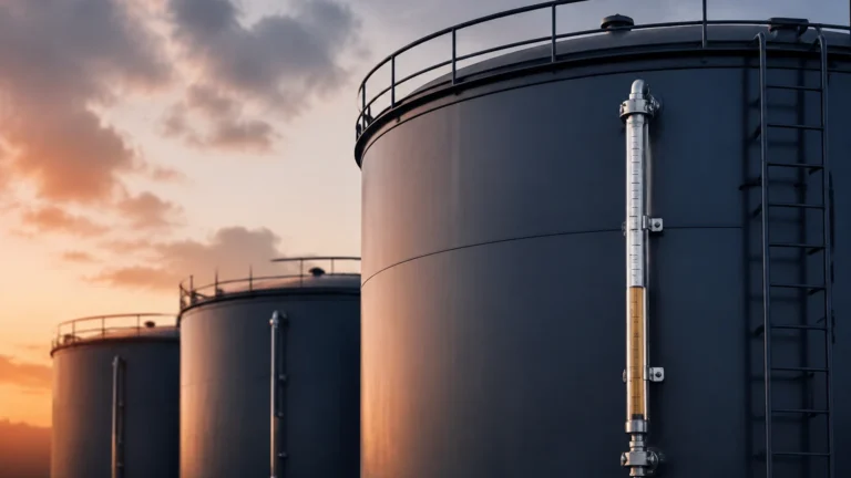
In complex industrial environments, flow and level measurement work in tandem. For instance, in a chemical blending tank, flow sensors measure the precise amount of each ingredient added, while a radar or ultrasonic level sensor monitors the total volume in the tank.
This "mass balance" approach is vital for safety and inventory control. If the flow sensor indicates that 500 liters have been added, but the level sensor shows an increase of 600 liters, it may indicate a leak from another valve or a calibration error in one of the instruments. For comprehensive solutions in tank monitoring and process automation, engineers often consult the Main Page of specialized instrument manufacturers like Welk to ensure that flow and level technologies are properly matched for the application.
Frequently Asked Questions (FAQs)
Q: Can mechanical flow sensors be used for steam?
A: Yes, specifically designed turbine meters and vortex shedding meters (which are sometimes categorized with mechanicals) can handle high-temperature steam, but they require specialized materials and construction to withstand the thermal stress.
Q: How often should a mechanical flow sensor be calibrated?
A: For non-critical water applications, every 2-3 years may suffice. For high-value custody transfer (like fuel or expensive chemicals), annual or even semi-annual calibration is standard.
Q: What happens if the flow exceeds the maximum rating of the sensor?
A: Over-speeding a mechanical sensor can lead to catastrophic failure. In a turbine meter, the centrifugal forces can cause the rotor blades to break off, potentially damaging downstream equipment.
Q: Do mechanical flow sensors require a power supply?
A: Purely mechanical meters with a local dial (like many rotameters or water meters) do not require power. However, if you need to send data to a PLC or SCADA system, the transmitter attached to the sensor will require a standard 24V DC power supply.
Conclusion
The mechanical flow sensor remains a vital tool in the engineer's arsenal. By understanding the specific physics of turbine, paddle wheel, and positive displacement technologies, users can select the most reliable instrument for their specific fluid and environmental conditions. When combined with rigorous installation practices and integrated with reliable level measurement systems, these sensors provide the data necessary for efficient, safe, and profitable industrial operations.