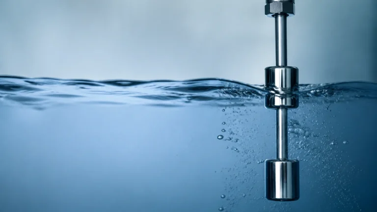
Meterline
Meterline
In the field of industrial process control, the accuracy of a level measurement system is fundamentally dependent on the integrity of the "meterline"—the vertical or linear axis along which a sensor transmits and receives signals or detects physical changes. Whether managing a chemical reactor, a water treatment facility, or an oil storage tank, establishing a precise reference line and understanding how different technologies interact with this path is essential for operational safety and efficiency.
Welk, as a professional manufacturer of industrial level measurement instruments, provides a diverse range of sensors designed to maintain high-performance standards across various meterline configurations. This guide explores the principles of these technologies, how to select the appropriate instrument, and the critical installation factors that ensure long-term reliability.
Understanding Measurement Principles
Before selecting a specific instrument, engineers must understand the physical principles that govern how a sensor interprets the level along the intended meterline. Each technology interacts differently with the process medium and the vessel environment.
Radar Level Measurement (Time of Flight)
Radar level meters operate on the Time of Flight (ToF) principle. The sensor emits high-frequency electromagnetic pulses (typically in the 26 GHz or 80 GHz range) that travel along the meterline toward the material surface. When these pulses hit a medium with a different dielectric constant, they are reflected back to the antenna. The instrument calculates the distance based on the time interval between transmission and reception. Because electromagnetic waves do not require a medium for propagation, radar is highly effective in vacuums and high-pressure environments.
Ultrasonic Level Measurement
Similar to radar, ultrasonic sensors use the ToF principle but employ sound waves instead of electromagnetic pulses. The transducer emits an ultrasonic pulse that travels through the air gap to the liquid surface. The reflection time is measured and converted into a distance value. However, because the speed of sound is affected by air temperature, these sensors usually include an integrated temperature probe to provide real-time compensation. The meterline for an ultrasonic sensor must be kept clear of physical obstructions that could cause false echoes.
Hydrostatic Level Measurement
Hydrostatic transmitters measure the pressure exerted by a liquid column at a specific depth. Based on the formula $P = \rho \cdot g \cdot h$ (where $P$ is pressure, $\rho$ is density, $g$ is gravity, and $h$ is height), the sensor determines the level relative to its mounting position. In this case, the meterline is effectively the vertical column of liquid above the diaphragm. This method is highly reliable for vented tanks where the density of the liquid remains constant.
Magnetic Level Gauges
Magnetic level gauges utilize the principle of buoyancy and magnetic coupling. A float containing a permanent magnet moves up and down a bypass chamber in response to the liquid level. Outside the chamber, a visual indicator or a transmitter tracks the float's position. The meterline here is the physical path of the float within the chamber, providing a robust, mechanical representation of the tank level without direct contact between the indicator and the process fluid.
Technology Selection Criteria
Choosing the right technology requires a detailed analysis of the process conditions. The following table provides a comparison of common level measurement technologies to assist in the selection process.
| Technology | Accuracy | Media Type | Max Temperature | Max Pressure | Best Use Case |
| :— | :— | :— | :— | :— | :— |
| Radar (80 GHz) | ±1 mm | Liquids/Solids | +250°C | 40 bar | High-precision chemical storage |
| Ultrasonic | ±0.25% of range | Water/Wastewater | +80°C | 3 bar | Open channel flow, sumps |
| Hydrostatic | ±0.1% to 0.5% | Clean Liquids | +100°C | 400 bar | Deep wells, vented tanks |
| Magnetic Gauge | ±5 mm | Corrosive Liquids | +400°C | 160 bar | Boiler drums, toxic storage |
| Level Switch | N/A (Point) | All | +150°C | 64 bar | Overfill protection |
When evaluating these options, it is recommended to Review product options and application support on the Welk Main Page to ensure the specific model matches your chemical compatibility and range requirements.
Critical Installation Considerations
A perfectly calibrated instrument will fail to provide accurate data if the installation ignores the physical constraints of the meterline. Engineers should adhere to the following guidelines during the design and mounting phase:
1. Dead Zones (Blocking Distance)
Every non-contact sensor (radar and ultrasonic) has a "dead zone" or blocking distance immediately below the transducer face. In this zone, the sensor cannot accurately process reflections because the pulse is still being transmitted. For example, if an ultrasonic sensor has a 0.3 m (300 mm) dead zone, the maximum liquid level must never reach within 0.3 m of the sensor face. If the tank must be filled to the top, a nozzle extension or a different technology should be used.
2. Nozzle Dimensions
When mounting a sensor on a nozzle, the diameter and height of the nozzle must be considered. If the nozzle is too narrow or too long, the signal may reflect off the nozzle walls before reaching the tank interior, creating "ringing" or false signals. For 80 GHz radar, smaller nozzles (e.g., DN50) are often acceptable due to the narrow beam angle, whereas ultrasonic sensors typically require wider openings.
3. Avoiding Obstructions
The meterline must be free of internal tank structures such as agitators, heating coils, ladders, and reinforcement struts. If an obstruction is unavoidable, many modern radar sensors offer "false echo suppression" software, allowing the user to map out static reflections. However, it is always best practice to mount the sensor at least 200 mm to 500 mm away from the tank wall to minimize side-wall interference.
4. Orientation and Alignment
For radar and ultrasonic sensors, the transducer face must be parallel to the liquid surface. Even a few degrees of tilt can cause the reflected signal to bounce away from the receiver, leading to signal loss. In applications involving solids (like grain or powders), an adjustable flange may be necessary to align the sensor with the angle of repose of the material.
Limitations and Environmental Factors
No single level measurement technology is universal. Understanding the limitations of the meterline environment is crucial for avoiding common pitfalls:
* Foam and Turbulence: Heavy foam can absorb ultrasonic and radar signals, leading to inaccurate readings. In such cases, a guided wave radar (GWR) or a hydrostatic transmitter is often preferred.
* Vapor and Condensation: High concentrations of steam or chemical vapors can attenuate ultrasonic signals. Radar is generally unaffected by vapors, but heavy condensation on the antenna face can still cause signal degradation. Welk offers specialized antenna designs (like PTFE drop antennas) to shed condensation effectively.
* Density Fluctuations: Hydrostatic and magnetic level gauges are sensitive to changes in liquid density. If the temperature of the fluid changes significantly, the density will shift, causing an error in the height calculation. For processes with varying densities, radar is the more reliable choice as it is independent of the medium's physical weight.
Frequently Asked Questions (FAQ)
Q: How does the dielectric constant (DK) affect radar measurement?
A: The dielectric constant determines how much energy is reflected back to the sensor. Materials with a high DK (like water, DK ≈ 80) reflect signals very well. Materials with a low DK (like oils or solvents, DK < 2) reflect very little energy, requiring more sensitive radar units or guided wave systems to maintain a reliable meterline signal.
Q: Can I use an ultrasonic sensor in a vacuum?
A: No. Ultrasonic waves require a medium (air or gas) to travel. In a vacuum, there are no molecules to transmit the sound vibration, so the sensor will not function. Radar is the preferred non-contact method for vacuum applications.
Q: What is the maximum range for a standard hydrostatic transmitter?
A: Hydrostatic transmitters can measure ranges from as little as 1 m to over 200 m (approx. 0.1 bar to 20 bar). The limitation is usually the strength of the cable and the sensitivity of the pressure diaphragm.
Q: How do I handle measurement in tanks with heavy agitation?
A: For agitated liquids, a stilling well or a bypass chamber is often used to create a calm meterline. Alternatively, a radar sensor with high-speed processing and filtering algorithms can be used to average out the surface turbulence.
Conclusion
Maintaining a clear and accurately defined meterline is the cornerstone of effective industrial level management. By understanding the underlying physics of radar, ultrasonic, and hydrostatic technologies, and by following strict installation protocols, facilities can achieve high precision and long-term stability. For technical specifications and customized OEM/ODM solutions, engineers should consult the comprehensive resources available on the Welk Main Page to find the most cost-effective and reliable instrumentation for their specific industrial automation needs.