Non Contact Radar Level Measurement
Non Contact Radar Level Measurement
Non contact radar level measurement has become the benchmark for accuracy and reliability in modern industrial process control. Unlike traditional contact-based methods, such as floats or displacers, radar technology utilizes electromagnetic waves to determine the distance to a product surface without physical interaction. This characteristic makes it exceptionally suited for corrosive, viscous, or high-temperature media where mechanical wear would otherwise lead to frequent maintenance and instrument failure.
In the context of industrial automation, the shift toward non contact radar level measurement is driven by the need for high-precision data that remains stable regardless of changes in process pressure, temperature, or vapor composition. As a professional manufacturer, Welk provides a range of radar solutions designed to meet the rigorous demands of water treatment, chemical processing, and oil and gas industries. Understanding the underlying physics and engineering constraints is essential for selecting the correct instrument for a specific application.
Measurement Principles: How Non Contact Radar Works
Non contact radar level transmitters operate by emitting high-frequency microwave signals toward the material surface. These signals travel at the speed of light and are reflected back to the sensor's antenna when they encounter a change in the dielectric constant (relative permittivity) of the medium. The time it takes for the signal to return is directly proportional to the distance between the sensor and the material surface.
There are two primary methods used in industrial radar measurement: Pulse Radar and Frequency Modulated Continuous Wave (FMCW).
Pulse Radar Technology
Pulse radar, often referred to as "Time of Flight" (ToF), sends out short microwave pulses at a fixed frequency. The transmitter measures the time interval between the emission and the reception of the reflected pulse. While effective for many standard applications, pulse radar can sometimes struggle with low-dielectric materials or environments with significant surface turbulence, as the signal-to-noise ratio is lower compared to modern alternatives.
FMCW (Frequency Modulated Continuous Wave)
FMCW radar is the current industry standard for high-precision non contact radar level measurement. Instead of sending discrete pulses, the transmitter emits a continuous signal with a frequency that changes linearly over time (a frequency sweep). The reflected signal is received and compared to the signal currently being emitted. The difference in frequency—known as the beat frequency—is proportional to the travel time and, therefore, the distance.
FMCW offers several advantages, including better signal processing and the ability to distinguish the true level from false echoes caused by tank internals like agitators or heating coils. High-frequency FMCW (specifically 80GHz) allows for a much narrower beam angle, which is critical for complex vessel geometries.
Key Evaluation Criteria for Radar Selection
Selecting the appropriate radar transmitter requires a thorough analysis of the process environment. The following factors are the most critical when evaluating a non contact radar level measurement system.
Frequency and Beam Angle
The frequency of the radar signal determines the beam angle. A higher frequency, such as 80GHz, produces a narrower, more focused beam compared to 6GHz or 26GHz models.
- Narrow Beam (80GHz): Ideal for tall, narrow tanks or vessels with many internal obstructions. The narrow beam avoids hitting the tank walls or internal pipes, reducing the risk of false reflections.
- Wide Beam (26GHz): Often used in larger storage tanks or open-air applications where obstructions are less of a concern.
Dielectric Constant (dk)
The dielectric constant of the medium is the most significant factor affecting signal reflection. Materials with a high dielectric constant, such as water (dk ≈ 80), reflect signals very strongly. Hydrocarbons, oils, and some solids have low dielectric constants (dk < 2), which absorb more of the radar energy and reflect less back to the sensor. For low-dk materials, high-sensitivity FMCW radar is necessary to ensure a reliable reading.
Process Conditions
Temperature and pressure do not directly affect the speed of the microwave signal, which is a major advantage over ultrasonic sensors. However, extreme conditions can affect the physical integrity of the sensor's antenna. Welk offers specialized antenna materials, such as PTFE or ceramics, to withstand aggressive chemicals and temperatures exceeding 200°C (392°F).
Comparison Table: 26GHz vs. 80GHz Radar
| Feature | 26GHz Non Contact Radar | 80GHz Non Contact Radar |
| :— | :— | :— |
| Beam Angle | Typically 8° to 20° | Typically 3° to 6° |
| Accuracy | ±3 mm to ±5 mm | ±1 mm to ±2 mm |
| Measuring Range | Up to 30 meters (98 ft) | Up to 120 meters (393 ft) |
| Obstruction Handling | Moderate; requires clear path | Excellent; avoids internals easily |
| Dust/Steam Penetration | Good | Excellent |
| Antenna Size | Larger (typically 2" to 4") | Smaller (can be < 1") |
| Best Application | Large storage tanks, simple liquids | Small vessels, solids, narrow nozzles |
Installation Considerations and Best Practices
Correct installation is paramount for the success of non contact radar level measurement. Even the most advanced 80GHz transmitter will fail if mounted incorrectly.
1. Nozzle Height and Diameter: The antenna should ideally extend past the bottom of the mounting nozzle to prevent signal interference within the nozzle itself. If the nozzle is very long, a radar with a lens antenna or a specific extension should be used.
2. Positioning: The sensor should not be mounted in the center of a domed tank, as this can cause multiple reflections that confuse the processor. It should also be kept away from the tank wall (typically at least 200mm or 8 inches) to avoid signal attenuation.
3. Inflow Streams: Never mount the radar directly above the point where product enters the tank. The turbulence and falling material will create significant noise and may lead to erratic readings.
4. Internal Obstructions: While modern software can perform "False Echo Suppression" to map out fixed obstructions like ladders or pipes, it is always best to choose a mounting location with a clear line of sight to the material surface.

Limitations and Challenges
While highly versatile, non contact radar level measurement is not a universal solution for every process. Engineers must be aware of the following limitations:
* Heavy Foam: Dense, thick foam can absorb the radar signal entirely, preventing any reflection from reaching the sensor. In these cases, a guided wave radar or a different measurement technology may be required.
* Extreme Turbulence: While radar handles surface ripples well, extreme boiling or violent agitation can scatter the signal. Using a stilling well or bypass chamber can mitigate this issue.
* Vacuum Conditions: Microwave signals travel perfectly in a vacuum, but the mechanical seals of the radar must be rated for vacuum service to prevent air ingress or sensor damage.
* Caking and Buildup: If the material is prone to sticking and creates a thick crust on the antenna lens, signal strength will degrade. For these applications, radars with integrated purging systems or non-stick PTFE lenses are recommended.
Applications in Process Industries
Non contact radar is utilized across a vast spectrum of industries due to its non-intrusive nature.
Water and Wastewater Treatment
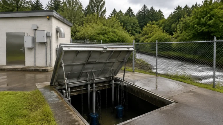
In wastewater applications, radar is used to measure levels in open channels, wet wells, and chemical storage tanks (such as sodium hypochlorite). Because the sensor does not touch the liquid, it is not affected by the grease, debris, or corrosive gases common in these environments.
Chemical and Petrochemical
For acids, bases, and solvents, non contact radar provides a safe measurement solution that keeps the process hermetically sealed. In the oil and gas sector, radar is used for both process control in separators and high-accuracy custody transfer in large storage tanks.
Solids and Powders
Measuring the level of grain, cement, or plastic pellets in tall silos is a classic challenge. High-frequency 80GHz radar is particularly effective here because the narrow beam can penetrate dust and reflect off the uneven, sloped surfaces of solid materials.
For more detailed technical specifications and to explore specific model ranges, engineers are encouraged to visit the Main Page to review product options and application support provided by Welk.
Frequently Asked Questions (FAQ)
Q: Does the density of the liquid affect radar accuracy?
A: No. Unlike hydrostatic level transmitters, radar measurement is independent of the density, pressure, and temperature of the medium. It only depends on the dielectric constant.
Q: Can non contact radar measure through a plastic tank lid?
A: Yes. If the tank is made of a non-conductive material like polyethylene or fiberglass, the radar signal can pass through the top of the tank, allowing for measurement without even cutting a hole in the vessel.
Q: How often does a radar level meter need calibration?
A: Because there are no moving parts and the technology is digital, radar sensors are extremely stable. Most units require only an initial setup and can run for years without recalibration, provided there is no significant buildup on the antenna.
Q: What is "False Echo Suppression"?
A: This is a software feature where the radar "learns" the environment of an empty tank. It identifies static reflections from internal structures and ignores them during operation, focusing only on the moving reflection from the material surface.
Conclusion
Non contact radar level measurement represents the pinnacle of current level sensing technology. By eliminating physical contact with the process media, it reduces maintenance costs and increases plant safety. Whether dealing with the extreme dust of a cement silo or the corrosive environment of a chemical reactor, selecting a radar with the appropriate frequency and antenna design ensures long-term operational success. For those looking to integrate these solutions into their automation systems, consulting with a specialized manufacturer like Welk ensures that the equipment is tailored to the specific dielectric and mechanical requirements of the project.