Non Invasive Ultrasonic Flow Meter
Non Invasive Ultrasonic Flow Meter
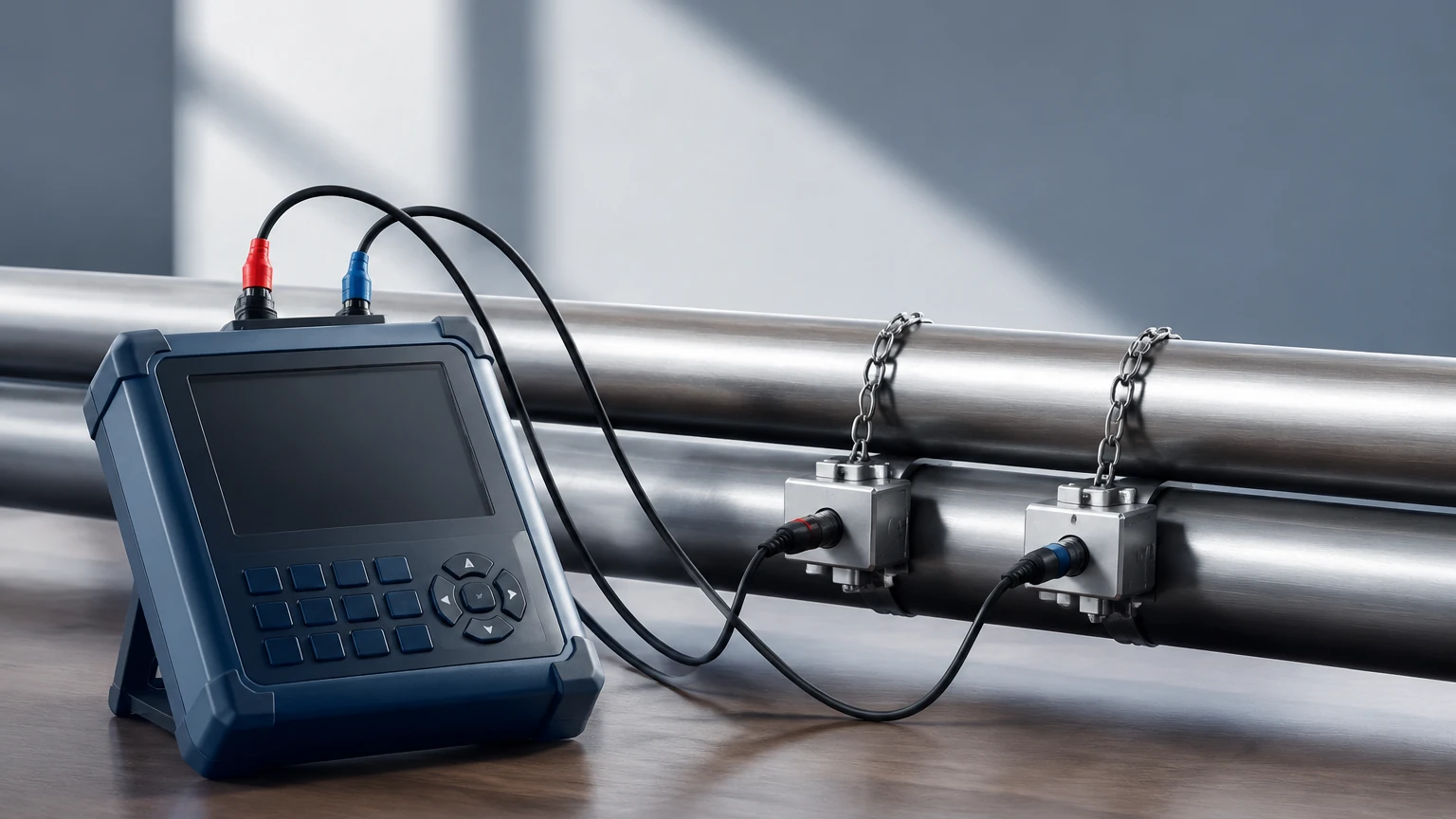
In the landscape of industrial process control, the ability to measure fluid velocity without breaching the integrity of the piping system is a significant advantage. The non invasive ultrasonic flow meter, often referred to as a clamp-on flow meter, has become a staple in sectors ranging from water treatment to chemical processing. By utilizing acoustic waves to determine flow rates, these instruments eliminate the risks of leakage, pressure drops, and contamination associated with inline sensors.
As a professional manufacturer of industrial measurement instruments, Welk provides high-precision solutions designed for the rigors of industrial automation. Understanding the underlying physics and application constraints is essential for engineers tasked with selecting the right instrumentation for their facilities.
Measurement Principles: Transit-Time vs. Doppler
Non-invasive ultrasonic flow measurement relies on two primary physical principles. Selecting the correct method depends entirely on the characteristics of the fluid being measured.
Transit-Time Method
Transit-time ultrasonic flow meters are the most common type used in industrial applications involving clean liquids. This method utilizes a pair of transducers, each acting as both a transmitter and a receiver. One transducer sends a signal downstream, while the other sends a signal upstream.
Because the fluid is moving, the sound wave traveling in the direction of the flow moves faster than the wave traveling against it. The meter measures the precise time difference (delta-T) between these two signals. This time difference is directly proportional to the velocity of the fluid.
* Best for: Water, oils, chemicals, and liquids with less than 2% suspended solids or aeration.
* Key Advantage: High accuracy in clean fluid environments.
Doppler Effect Method
The Doppler flow meter operates on the principle of frequency shift. A transducer transmits an ultrasonic signal into the pipe at a known frequency. This signal reflects off particles, bubbles, or turbulence within the moving fluid. Because the reflectors are moving, the frequency of the reflected signal is shifted (the Doppler effect).
The flow meter calculates the velocity by measuring the difference between the transmitted and received frequencies.
* Best for: Slurries, wastewater, aerated liquids, and fluids with significant suspended solids (typically >100 ppm).
* Key Advantage: Ability to measure "dirty" liquids that would attenuate transit-time signals.
Technical Selection Criteria
Choosing a non invasive ultrasonic flow meter requires a detailed analysis of the pipe and the process fluid. Unlike level measurement instruments found on the Main Page, flow meters are highly sensitive to the internal geometry of the conduit.
Pipe Material and Condition
The pipe must be capable of conducting ultrasonic waves. While most metals (carbon steel, stainless steel, ductile iron) and plastics (PVC, PE, PVDF) are excellent conductors, certain materials like concrete or heavily corroded pipes can scatter or absorb the signal.
| Feature | Requirement / Consideration |
| :— | :— |
| Pipe Diameter | Typically ranges from DN15 (1/2") to DN6000 (240"). |
| Wall Thickness | Must be known precisely for transit-time calculations. |
| Liner Material | Liners must be well-bonded to the pipe wall; air gaps between the liner and pipe will block the signal. |
| Fluid Temperature | Standard transducers handle up to 80°C; high-temp versions reach 150°C or higher. |
Fluid Properties
The fluid must be sonically conductive. Most liquids are suitable, but highly viscous fluids or those with excessive gas bubbles can pose challenges. For applications involving high-concentration slurries, a Doppler-based system is mandatory.
Installation Best Practices
The performance of a non invasive ultrasonic flow meter is heavily dependent on the quality of the installation. Because the transducers are mounted on the exterior of the pipe, the acoustic coupling and the flow profile are critical factors.
Straight Pipe Requirements
To ensure a stable and predictable flow profile, transducers should be installed on a straight section of pipe. The standard engineering guideline is the "10D and 5D" rule:
1. Upstream: At least 10 pipe diameters of straight pipe after any elbow, valve, or pump.
2. Downstream: At least 5 pipe diameters of straight pipe before any subsequent fittings.
If the flow is highly turbulent (e.g., immediately after a dual-plane elbow), the upstream requirement may increase to 20D or 40D.
Transducer Mounting Configurations
There are three primary mounting methods for clamp-on sensors:
1. V-Method: The most common method for pipe diameters from DN25 to DN400. The signal bounces off the opposite wall once. It is easy to install and provides good accuracy.
2. Z-Method: Used for large pipes (above DN400) or where the fluid is slightly attenuating. Transducers are placed on opposite sides of the pipe, and the signal crosses the pipe only once.
3. W-Method: Used for very small pipes (below DN50). The signal bounces three times, increasing the transit time and improving resolution for low-flow conditions.
Acoustic Coupling
An ultrasonic signal cannot travel through air gaps. A coupling agent (grease, gel, or silicone) must be applied between the transducer face and the pipe surface. For permanent installations, solid coupling pads or specialized epoxies are often used to prevent the couplant from drying out over time.
Operational Limitations and Common Risks
While non-invasive meters offer ease of use, engineers must be aware of potential pitfalls that can lead to inaccurate readings.
* Aeration and Cavitation: If a pump is sucking air or if there is a significant pressure drop causing cavitation, the resulting bubbles will reflect or scatter ultrasonic waves, leading to signal loss (Signal Strength Error).
* Partially Filled Pipes: Ultrasonic flow meters assume the pipe is 100% full. If the pipe is only partially full, the meter will calculate the velocity based on a full cross-sectional area, resulting in a significant overestimation of the flow rate.
* Scaling and Buildup: Internal scaling or tuberculation in older iron pipes creates an uneven surface that scatters the signal. In such cases, the pipe may need to be cleaned or a different measurement point selected.
* Wall Thickness Uncertainty: In transit-time flow meters, an error in the entered pipe wall thickness translates directly into a flow velocity error. Using an ultrasonic thickness gauge to verify the pipe wall before installation is a recommended best practice.
Comparison with Other Technologies
To provide context for selection, it is helpful to compare the non invasive ultrasonic flow meter with other common industrial flow technologies.
| Technology | Non-Invasive Ultrasonic | Electromagnetic (Magmeter) | Vortex Shedding |
| :— | :— | :— | :— |
| Installation | External (Clamp-on) | Inline (Flanged/Wafer) | Inline |
| Fluid Conductivity | Not required | Must be >5 μS/cm | Not required |
| Pressure Drop | Zero | Zero | Moderate |
| Maintenance | Very Low | Low | Moderate |
| Initial Cost | Moderate to High | Moderate | Moderate |
Frequently Asked Questions (FAQ)
Q: Can I use a non-invasive flow meter on a pipe with a liner?
A: Yes, provided the liner is acoustically conductive and tightly bonded to the pipe wall. Materials like Teflon, rubber, and plastic liners are generally acceptable. If there is an air gap between the liner and the pipe, the signal will be blocked.
Q: How accurate are clamp-on ultrasonic flow meters?
A: In ideal conditions with a fully developed flow profile and accurate pipe parameters, transit-time meters can achieve accuracies of ±0.5% to ±1.0% of flow rate. Doppler meters are generally less accurate, typically ranging from ±2% to ±5%.
Q: Does the pipe material affect the measurement?
A: Yes. The meter must know the sound velocity of the pipe material to calculate the refraction angle of the ultrasonic beam. Most modern meters have a built-in library of common materials (Steel, PVC, Copper, etc.).
Q: Can these meters measure gas flow?
A: While there are specialized high-power ultrasonic meters for gas, standard industrial clamp-on meters are designed for liquids. Gas has much lower acoustic impedance, making it difficult for signals to penetrate the pipe wall and the gas medium effectively without specialized equipment.
Conclusion
The non invasive ultrasonic flow meter represents a versatile and cost-effective solution for modern industrial environments where process downtime is not an option. By eliminating the need to cut pipes or stop flow, these instruments provide a level of flexibility that traditional inline meters cannot match.
When integrated with other process instruments, such as the radar or hydrostatic sensors found in our broader catalog, they form a robust data foundation for industrial automation. For technical specifications and to explore our full range of measurement solutions, please visit our Main Page.
Proper selection, based on a clear understanding of transit-time versus Doppler principles and rigorous attention to installation geometry, ensures that these meters provide reliable data for years of operation. Whether for water management, chemical dosing, or cooling system monitoring, the clamp-on ultrasonic meter remains a premier choice for non-intrusive flow analysis.