Nuclear Pressure Transmitter
Nuclear Pressure Transmitter
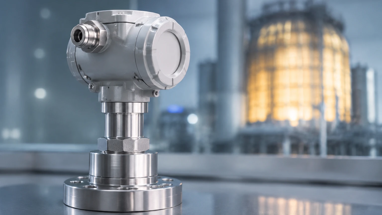
In the demanding environment of a nuclear power plant (NPP), the nuclear pressure transmitter serves as a critical component for both process control and safety systems. Unlike standard industrial sensors, these devices must operate with absolute reliability under extreme conditions, including high radiation levels, seismic activity, and potential Loss of Coolant Accident (LOCA) scenarios. This guide provides a technical overview of the measurement principles, selection criteria, and installation requirements for pressure transmitters in nuclear applications.
Measurement Principles in Nuclear Environments
A nuclear pressure transmitter converts physical pressure—whether gauge, absolute, or differential—into an electrical signal, typically a 4-20 mA analog output. Given the safety-critical nature of these applications, the sensing technology must be robust against drift and environmental interference.
Capacitive Sensing
Capacitive pressure sensors utilize a sensing diaphragm positioned between two fixed capacitor plates. As pressure is applied, the diaphragm deflects, changing the capacitance. In nuclear applications, this technology is favored for its high accuracy and long-term stability. The electronics are often separated from the sensor head or heavily shielded to withstand radiation-induced degradation.
Piezoresistive and Strain Gauge Sensing
These sensors rely on the change in electrical resistance of a material when subjected to mechanical strain. In a nuclear pressure transmitter, the strain gauges are often bonded to a metal diaphragm. While highly sensitive, these units require specialized materials to prevent the "embrittlement" of the bonding agents when exposed to high neutron flux or gamma radiation.
Differential Pressure (DP) for Level and Flow
In many nuclear systems, pressure transmitters are used indirectly to measure fluid level in pressurized vessels or flow rates in cooling loops. By measuring the pressure drop across an orifice plate or the hydrostatic head of a tank, engineers can derive critical process data. For broader industrial level measurement needs outside the nuclear island, such as water treatment or chemical storage, engineers often consult the Main Page of specialized manufacturers like Welk to review standard industrial radar or ultrasonic options.
Design Requirements for Nuclear Safety
The engineering of a nuclear pressure transmitter is governed by strict international standards, most notably those established by the IEEE and ASME. These ensure that the device will function during and after a design-basis event.
Environmental Qualification (IEEE 323)
IEEE 323 outlines the requirements for qualifying Class 1E equipment (safety-related) for nuclear power generating stations. A transmitter must be tested to prove it can withstand the "Total Ionizing Dose" (TID) it will encounter over its 40-to-60-year service life. This often involves testing up to 1 megarad (10 kGy) or higher, depending on the installation zone.
Seismic Qualification (IEEE 344)
Nuclear facilities are built to withstand earthquakes. Transmitters must be seismically qualified through shake-table testing to ensure that structural integrity and functional performance are maintained during a Safe Shutdown Earthquake (SSE).
Materials and Construction
* Wetted Parts: Typically 316L Stainless Steel, Hastelloy, or Monel to resist corrosion from borated water or primary coolants.
* Seals: Ethylene Propylene (EPDM) or specialized metallic O-rings are used, as standard Viton or Nitrile seals may fail under high radiation.
* Electronics: Radiation-hardened (Rad-Hard) components or remote-mounted electronics packages are common to protect sensitive semiconductors.
Selection Criteria for Nuclear Pressure Transmitters
When specifying a nuclear pressure transmitter, engineers must balance technical performance with regulatory compliance. The following table summarizes key evaluation parameters:
| Parameter | Requirement Detail | Why it Matters |
| :— | :— | :— |
| Accuracy | ±0.075% to ±0.25% of span | Ensures precise control of reactor coolants. |
| Radiation Tolerance | Up to 2000 kGy (200 Mrad) | Prevents signal drift or total failure in the containment area. |
| Response Time | < 100 milliseconds | Critical for rapid reactor trip systems. |
| Temperature Range | Up to 200°C (392°F) | Must survive steam release during a LOCA event. |
| Pressure Limits | Up to 250 bar (25 MPa) | Necessary for high-pressure primary loops. |
Application Zones
1. Inside Containment: Requires the highest level of qualification (Class 1E). Must be LOCA-qualified.
2. Outside Containment: Often requires seismic qualification but lower radiation resistance.
3. Balance of Plant (BOP): Standard industrial-grade transmitters may be used for non-safety systems, provided they meet site-specific mechanical standards.
Installation and Impulse Line Configuration
The physical installation of a nuclear pressure transmitter is as vital as the device itself. Incorrect mounting can lead to air pockets or sediment buildup, resulting in false readings.
Impulse Piping
Impulse lines connect the process pipe to the transmitter. In nuclear steam applications, these lines must be sloped correctly (typically 1:12 slope) to allow non-condensable gases to vent back into the process or to allow condensate to drain.
Manifolds and Isolation
Five-valve manifolds are standard for differential pressure applications. They allow for the isolation of the transmitter for calibration and the equalization of pressure to prevent over-ranging the sensor during startup. In nuclear environments, these manifolds must also be qualified for seismic and pressure boundary integrity.
Remote Diaphragm Seals
In cases where the process fluid is highly corrosive or contains particulates, remote diaphragm seals are used. A capillary tube filled with a stable fluid (like silicone oil or Halocarbon) transmits the pressure from the process to the sensor. In nuclear settings, the fill fluid must be selected for radiation stability to avoid gas evolution (outgassing) under irradiation.
Limitations and Operational Risks
Despite their robust design, nuclear pressure transmitters face several operational challenges:
* Hydrogen Permeation: In high-temperature nuclear water chemistry, hydrogen ions can permeate through metal diaphragms, causing signal offset or sensor failure. Gold-plating the diaphragms is a common mitigation strategy.
* Calibration Drift: Constant exposure to radiation and thermal cycling causes electronic components to age. Frequent "surveillance testing" is required by regulatory bodies to ensure the transmitter remains within its calibrated technical specifications.
* Installation Errors: Improperly bled impulse lines are a leading cause of sluggish response times in safety systems.
Comparison with Industrial Level Measurement
While nuclear pressure transmitters are specialized for the reactor core and primary loops, many auxiliary systems in a power plant utilize standard industrial level measurement technologies. For example, cooling water intake, chemical dosing tanks, and wastewater treatment systems often use ultrasonic or radar level sensors.
For engineers looking to source high-quality industrial level instruments for these non-nuclear-island applications, manufacturers like Welk provide a range of hydrostatic level transmitters and magnetic gauges. You can find detailed technical specifications for these industrial solutions on their Main Page.
Frequently Asked Questions
Q: How often should a nuclear pressure transmitter be calibrated?
A: Calibration intervals are typically dictated by the plant's Technical Specifications (Tech Specs), often ranging from every 18 to 24 months, coinciding with refueling outages.
Q: Can a standard industrial transmitter be used in a nuclear plant?
A: Only in non-safety-related (Non-Class 1E) applications. Any component used in safety-critical systems must undergo a rigorous "Commercial Grade Dedication" (CGD) process if it was not originally manufactured under a nuclear quality assurance program (like ASME NQA-1).
Q: What is the difference between a gauge and absolute pressure transmitter in this context?
A: Gauge pressure transmitters measure pressure relative to local atmospheric pressure, while absolute pressure transmitters measure relative to a full vacuum. Absolute transmitters are critical in nuclear systems for monitoring condenser vacuum and containment pressures where atmospheric fluctuations could introduce errors.
Q: What units are typically used for pressure in these guides?
A: While North American plants often use PSI (pounds per square inch), international and modern engineering standards favor metric units such as kPa (kilopascals) or bar (1 bar = 100 kPa).
Conclusion
The selection and maintenance of a nuclear pressure transmitter require a deep understanding of both mechanical engineering and nuclear physics. By adhering to IEEE qualification standards and ensuring precise installation through proper impulse line management, plant operators can maintain the high levels of safety required for nuclear power generation. For more general industrial level and pressure measurement guidance, professional engineering references and manufacturer resources remain the primary source for technical data.