Instrumentation and Calibration
Instrumentation and Calibration
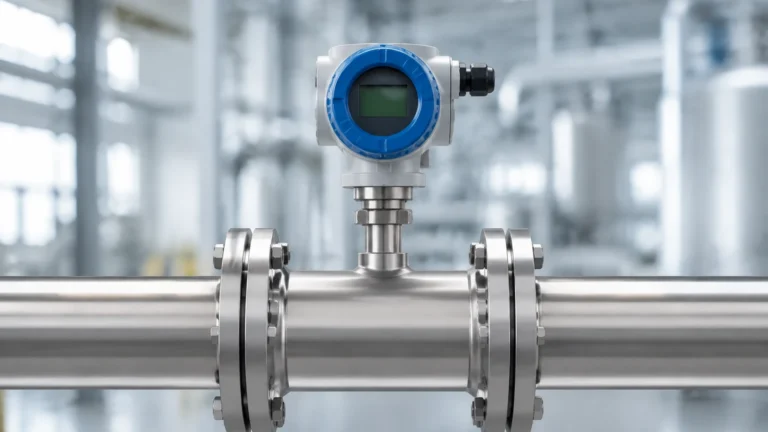
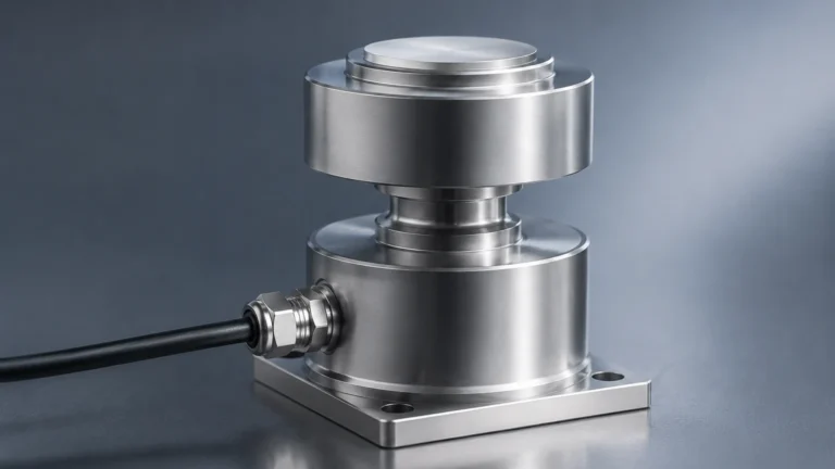
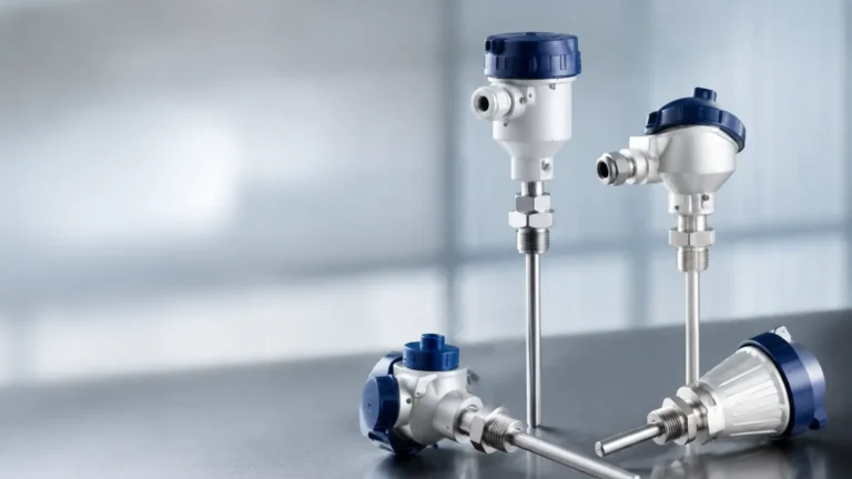
In the realm of industrial automation and process control, the accuracy of level measurement is fundamental to operational safety, efficiency, and regulatory compliance. Instrumentation and calibration form the dual pillars of this accuracy. While instrumentation refers to the physical devices—such as radar level meters, ultrasonic sensors, and hydrostatic transmitters—calibration is the essential process of verifying and adjusting these instruments to ensure their output matches a known standard. For engineers and facility managers, understanding the interplay between device physics and periodic maintenance is critical for optimizing plant performance.
Welk, as a professional manufacturer of industrial level measurement instruments, provides high-precision solutions designed to meet the rigorous demands of water treatment, chemical processing, and oil and gas industries. Ensuring these instruments perform at their peak requires a deep understanding of their underlying principles and the specific requirements of their calibration cycles.
Principles of Industrial Level Measurement
Before addressing calibration procedures, it is necessary to understand how different level measurement technologies function. Each principle has unique characteristics that influence how the device is commissioned and maintained.
Radar Level Measurement (ToF)
Radar level meters utilize Time of Flight (ToF) technology. High-frequency microwave pulses (typically 26GHz or 80GHz) are emitted from the antenna, reflected off the medium surface, and received by the sensor. The distance is calculated based on the time interval and the constant speed of light.
* Non-contact Radar: Ideal for corrosive or high-temperature liquids where physical contact with the sensor is undesirable.
* Guided Wave Radar (GWR): Uses a probe to guide the signal, making it more effective in low-dielectric fluids or applications with heavy foam.
Ultrasonic Level Sensors
Similar to radar, ultrasonic sensors use ToF but rely on sound waves rather than electromagnetic pulses. A piezoelectric crystal converts electrical energy into mechanical sound waves. These waves bounce off the liquid surface and return to the transducer. Because sound speed is affected by air temperature, these instruments typically include integrated temperature compensation.
Hydrostatic Level Transmitters
Hydrostatic measurement is based on the principle that the pressure at the bottom of a liquid column is proportional to the height of the liquid and its density ($P = \rho \cdot g \cdot h$). A pressure sensor (often a diaphragm) measures the head pressure of the liquid. This method is highly reliable for vented tanks and deep wells but requires accurate density data for precise calibration.
Magnetic Level Gauges and Switches
Magnetic level gauges utilize a float containing a permanent magnet. As the liquid level changes, the float moves, causing magnetic flags on an external scale to rotate. This provides a visual indication and can be paired with reed switches or transmitters for remote monitoring. Calibration for these devices often involves verifying the float's buoyancy relative to the specific gravity of the process fluid.
The Critical Role of Instrumentation and Calibration
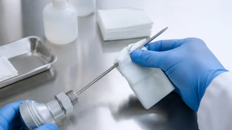
Instrumentation and calibration are not one-time events but ongoing requirements for process integrity. Even the most advanced sensors can experience "drift" over time due to electronic component aging, environmental stress, or mechanical wear.
Defining Calibration Parameters
Calibration involves comparing the instrument's reading against a reference standard. Key terms include:
* Zero Point: The output signal (e.g., 4mA) when the tank is empty.
* Span: The range between the minimum and maximum measurable levels.
* Linearity: The consistency of the instrument’s accuracy across its entire range.
* Hysteresis: The difference in readings when the level is rising versus when it is falling.
Calibration Methods
1. Dry Calibration: Performed without process fluid. For radar and ultrasonic units, this involves configuring the "empty" and "full" distances via software based on the tank geometry.
2. Wet Calibration: The most accurate method, involving actual liquid. The tank is filled to known levels, and the instrument output is adjusted to match the physical measurements.
3. Bench Calibration: The instrument is removed from the process and tested in a controlled laboratory environment using a calibration rig.
Selection Criteria for Level Instruments
Choosing the correct instrument is the first step in reducing calibration frequency and ensuring long-term stability. The following table provides a comparison of common technologies based on industrial application needs.
| Technology | Best For | Advantages | Limitations |
| :— | :— | :— | :— |
| 80GHz Radar | Small tanks, agitated liquids | High precision, small beam angle | Higher initial cost |
| Ultrasonic | Water/Wastewater | Cost-effective, non-contact | Sensitive to foam and vacuum |
| Hydrostatic | Deep wells, open tanks | Simple installation, reliable | Affected by fluid density changes |
| Magnetic Gauge | High-pressure boilers | Visual and electronic output | Moving parts subject to scaling |
| Level Switch | Overfill protection | High reliability, low cost | Point measurement only |
When evaluating hardware, engineers should visit the Main Page to review detailed technical specifications and ensure the selected device matches the chemical compatibility and pressure ratings of the application.
Installation Considerations for Accuracy
Even a perfectly calibrated instrument will provide inaccurate data if installed incorrectly. Proper instrumentation and calibration practices begin with the physical mounting of the sensor.
* Nozzle Geometry: For radar and ultrasonic sensors, the nozzle height and diameter must not interfere with the signal beam. Internal obstructions like ladders or agitators should be mapped out using "false echo suppression" software.
* Dead Zones (Blocking Distance): Every non-contact sensor has a minimum distance (dead zone) near the antenna where measurement is impossible. The sensor must be mounted high enough to account for the maximum expected liquid level.
* Still Wells and Bypass Pipes: In turbulent applications, installing the sensor inside a stilling well or a bypass pipe can stabilize the liquid surface, providing a much cleaner signal for the instrument to process.
* Environmental Protection: While Welk instruments are designed for rugged environments, shielding sensors from direct solar heating or extreme vibration can extend the intervals between required calibrations.
Common Risks and Limitations
Understanding the limitations of instrumentation and calibration helps prevent process failures.
1. Dielectric Constant ($ε_r$): Radar signals rely on the dielectric constant of the medium. If the $ε_r$ is too low (e.g., certain oils or liquefied gases), the signal reflection may be too weak. Guided wave radar is often the solution here.
2. Vapor and Dust: High concentrations of dust or heavy steam can attenuate ultrasonic signals. In these environments, high-frequency radar is generally preferred.
3. Coating and Buildup: In sticky or crystallizing media, material can build up on the sensor face or float. This causes measurement lag or "frozen" readings. Regular maintenance and the use of non-stick coatings (like PTFE) are essential.
Frequently Asked Questions (FAQ)
Q: How often should I calibrate my level meters?
A: This depends on the industry and the criticality of the measurement. In regulated industries like pharmaceuticals, annual calibration is standard. In general water treatment, a check every 12 to 24 months may suffice unless drift is detected.
Q: Can I calibrate a hydrostatic transmitter if the liquid density changes?
A: Yes, but the instrument must be re-spanned. If the density of the fluid is variable, you may need a system that measures both pressure and temperature to calculate the corrected level.
Q: What is the difference between 26GHz and 80GHz radar?
A: 80GHz radar has a much narrower beam angle and higher resolution, making it better for tanks with many internal obstructions or for measuring through narrow nozzles. 26GHz is often sufficient for larger, open-space applications.
Q: Does foam affect all level sensors?
A: No. While foam can absorb ultrasonic and non-contact radar signals, hydrostatic transmitters and magnetic level gauges are largely unaffected by surface foam as they measure based on mass or buoyancy.
Conclusion
Effective instrumentation and calibration are essential for maintaining the safety and efficiency of modern industrial processes. By selecting the appropriate measurement principle—whether it be the precision of 80GHz radar or the robustness of hydrostatic pressure—and adhering to a rigorous calibration schedule, facilities can minimize downtime and ensure data integrity.
For technical support, custom OEM/ODM services, or to explore a comprehensive range of level measurement solutions, engineers are encouraged to consult professional manufacturers who prioritize accuracy and reliability in every component. Proper planning during the selection and installation phases will significantly reduce the long-term burden of maintenance and recalibration.