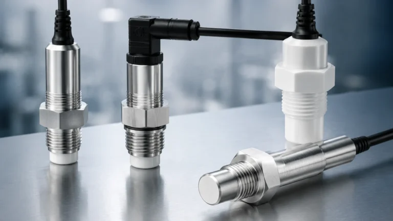
O Sensor
O Sensor
In the field of industrial automation and fluid management, the term "o sensor"—primarily referring to optical level sensors—represents a critical technology for point-level detection. Unlike continuous measurement technologies such as radar or ultrasonic transmitters, the o sensor is designed to provide highly accurate, rapid-response signals when a liquid reaches a specific threshold. These instruments are essential in protecting equipment from dry-running, preventing tank overfills, and managing complex liquid-liquid interfaces in chemical and water treatment processes.
As industrial environments become increasingly automated, the demand for compact, reliable, and maintenance-free sensing solutions has grown. This guide explores the engineering principles, selection criteria, and practical applications of the o sensor within the broader context of industrial level measurement.
Measurement Principles of the O Sensor
The operation of an optical o sensor is based on the principles of light refraction and reflection. Most industrial optical sensors consist of two primary internal components: an infrared Light Emitting Diode (LED) and a phototransistor (receiver). These components are housed within a transparent sensing tip, typically shaped as a prism or a dome.
The State of Reflection (Dry Condition)
When the sensor tip is surrounded by air or gas, the light emitted by the LED is reflected internally within the prism. Due to the difference in the refractive index between the sensor material (such as polysulfone or glass) and the surrounding air, the light travels back to the phototransistor. This completes the circuit and indicates a "dry" state.
The State of Refraction (Wet Condition)
When the liquid level rises and submerges the sensing tip, the refractive index at the interface changes. Because the refractive index of most liquids is much closer to that of the sensor tip material than air is, the light is no longer reflected internally. Instead, the light escapes or "leaks" into the liquid. The phototransistor detects a significant drop in light intensity, triggering a change in the output signal to indicate a "wet" state.
This solid-state approach eliminates the need for moving parts, which is a significant advantage over traditional float switches that may suffer from mechanical wear or jamming due to debris.
Technical Specifications and Selection Criteria
Selecting the correct o sensor requires a detailed understanding of the process media and the environmental conditions of the installation. Engineers must evaluate material compatibility, pressure ratings, and electrical output requirements to ensure long-term reliability.
Material Compatibility
The sensing tip is the only part of the instrument in direct contact with the process fluid. Common materials include:
* Polysulfone (PSU): A high-performance thermoplastic suitable for water, most acids, and bases. It is cost-effective but has limited resistance to certain organic solvents.
* Trogamid: Often used in applications involving oils and fuels where chemical resistance to hydrocarbons is paramount.
* Stainless Steel with Glass/Quartz Tip: Designed for high-pressure and high-temperature environments, or for use with aggressive chemicals that would degrade plastics.
Selection Table for Optical Level Sensors
| Feature | Plastic O Sensor (PSU/Trogamid) | Stainless Steel / Glass O Sensor |
| :— | :— | :— |
| Pressure Range | Up to 10 bar (1 MPa) | Up to 50 bar (5 MPa) or higher |
| Temperature Range | -20°C to +85°C | -40°C to +125°C |
| Chemical Resistance | Moderate (Water, Glycol, Dilute Acids) | High (Solvents, Concentrated Acids, Fuels) |
| Mounting Thread | M12, 1/2" NPT/G | 1/2" NPT/G, 3/4" NPT |
| Typical Application | HVAC, Leak Detection, Food & Beverage | Chemical Processing, Oil & Gas, Hydraulic Power |
For comprehensive system design and to explore how these sensors integrate with broader measurement arrays, engineers often consult the Main Page of specialized manufacturers to review product options and application support.
Industrial Applications of the O Sensor
The versatility of the o sensor allows it to be used across various industries where space is limited and precision is required.
1. Water and Wastewater Treatment
In water treatment facilities, optical sensors are frequently used for leak detection in double-walled tanks or as high-level alarms in chemical dosing skids. Their ability to ignore small amounts of foam—which can sometimes trigger ultrasonic sensors prematurely—makes them a robust choice for turbulent tanks.
2. Hydraulic and Lubrication Systems
In industrial machinery, maintaining the correct level of hydraulic fluid or lubricant is vital. The compact size of the o sensor allows it to be installed in small reservoirs or manifolds where a traditional magnetic level gauge or radar unit would be too large.
3. Chemical Processing
Because they can be manufactured from chemically inert materials, these sensors are ideal for monitoring the level of aggressive reagents. In these settings, the o sensor often acts as a redundant safety layer, providing an independent shut-off signal if the primary continuous level transmitter fails.
4. Laboratory and Medical Equipment
In precision laboratory equipment, such as analyzers or cooling baths, the o sensor provides a non-mechanical way to ensure liquid levels remain within strict tolerances, preventing air from entering pump lines.
Installation Considerations and Best Practices
Proper installation is critical to prevent false triggering and ensure the longevity of the o sensor. Engineers should adhere to the following guidelines:
1. Orientation: While optical sensors can be mounted horizontally, vertically, or at an angle, horizontal mounting is generally preferred to prevent liquid droplets from clinging to the tip and causing a "false wet" reading as the level recedes.
2. Avoidance of Reflective Surfaces: If the sensor is installed too close to a reflective tank wall or an internal baffle, the light escaping the tip may reflect off the surface and return to the receiver, causing a "false dry" signal. A minimum clearance of 15 mm to 20 mm is usually recommended.
3. Bubble Interference: Large air bubbles clinging to the sensor tip can mimic a dry state. In applications where aeration is common, the sensor should be placed in a stilling well or a low-turbulence area of the tank.
4. Wiring and Output: Ensure the electrical output (NPN, PNP, or Push-Pull) matches the input requirements of the PLC or control system. Most industrial o sensors operate on 10-30V DC power.

Limitations and Environmental Factors
Despite their advantages, the o sensor is not a universal solution for every application. Understanding its limitations is key to successful engineering.
* Coating and Viscosity: Highly viscous liquids or those that leave a thick film (such as heavy oils or syrups) can coat the sensing tip. This coating may hold enough light to prevent the sensor from switching back to a "dry" state when the level drops.
* Ambient Light Interference: Extremely high-intensity ambient light (such as direct sunlight or high-power halogen lamps) can occasionally interfere with the phototransistor. Most modern sensors use modulated infrared light to mitigate this, but shielded installation is still a best practice for outdoor use.
* Foam and Bubbles: While optical sensors are better than many technologies at ignoring light foam, extremely dense, opaque foam can sometimes cause a wet signal, while heavy aeration can cause a dry signal when the sensor is actually submerged.
Frequently Asked Questions (FAQ)
Q: Can an o sensor detect the interface between two liquids?
A: Yes, provided the two liquids have significantly different refractive indices. For example, an optical sensor can often distinguish between oil and water, making it useful in oil-water separators.
Q: Does the color of the liquid affect the sensor's performance?
A: Generally, no. Because the sensor operates on the principle of refraction rather than simple light blocking, even highly opaque or dark liquids will cause the light to escape the prism tip and trigger a signal.
Q: How do I clean an o sensor if it becomes coated?
A: Cleaning should be done with a soft cloth and a solvent compatible with the tip material (e.g., isopropyl alcohol for glass or PSU). Avoid abrasive cleaners that could scratch the optical surface, as scratches can cause light scattering and lead to inaccurate readings.
Q: Is the o sensor suitable for explosive atmospheres?
A: Many manufacturers offer intrinsically safe (Ex ia) or explosion-proof versions of these sensors. Always check the ATEX, IECEx, or local certification before installing a sensor in a hazardous area.
Conclusion
The o sensor is a fundamental tool in the industrial instrumentation toolkit, offering a blend of precision, speed, and reliability that mechanical switches cannot match. By understanding the optical principles behind its operation and carefully selecting materials based on the process environment, engineers can implement level control solutions that enhance both safety and efficiency. For those seeking to integrate these point-level devices into a complete automation strategy, consulting professional resources and technical documentation on the Main Page is the recommended next step for ensuring application success.