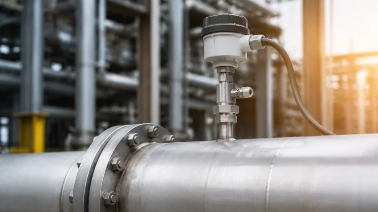
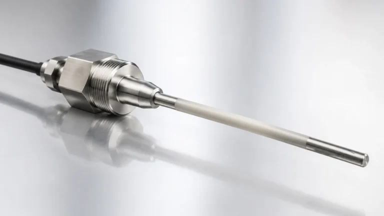
Oil Level Transmitter
Oil Level Transmitter
In industrial automation and process control, the accurate measurement of oil levels is a fundamental requirement for operational safety, inventory management, and environmental protection. An oil level transmitter is a sophisticated instrument designed to provide continuous level monitoring of various petroleum-based fluids, lubricants, and hydraulic oils. Unlike simple point-level switches, these transmitters output a continuous signal—typically 4-20mA, HART, or RS485—representing the exact fluid level within a tank or vessel.
Selecting the appropriate oil level transmitter requires a deep understanding of the physical properties of the medium, the vessel geometry, and the environmental conditions. Oils present unique challenges compared to water, including varying dielectric constants, changes in viscosity with temperature, and the potential for vapor or foam formation. This guide explores the primary measurement principles, selection criteria, and installation best practices for industrial oil level transmitters.
Understanding Oil Level Measurement Technologies
There is no single "universal" sensor for oil measurement. Different technologies excel depending on whether the application involves crude oil storage, refined fuel distribution, or high-pressure hydraulic systems. Before making a selection, engineers must evaluate the measurement principle that best aligns with their process requirements.
Radar Level Measurement (Non-Contact)
Radar level transmitters, particularly those operating at 26GHz or 80GHz frequencies, are widely considered the gold standard for oil level measurement. They utilize the Time-of-Flight (ToF) principle. The sensor emits a high-frequency microwave pulse that travels to the oil surface, reflects off the liquid, and returns to the receiver.
Because radar waves travel at the speed of light and do not require a physical medium, they are unaffected by temperature fluctuations, pressure changes, or the presence of heavy vapors. However, oils typically have a low dielectric constant (εr), usually ranging from 1.8 to 2.5. This means the reflected signal is weaker than it would be for water. Advanced signal processing in modern Main Page instruments allows for reliable tracking even with low-reflectivity fluids.
Ultrasonic Level Measurement
Ultrasonic transmitters function similarly to radar but use sound waves instead of microwaves. A piezoelectric crystal within the transducer converts electrical energy into mechanical sound pulses. These pulses bounce off the oil surface and return to the sensor.
Ultrasonic sensors are cost-effective and suitable for many atmospheric oil storage applications. However, they have significant limitations in oil environments. The speed of sound is highly dependent on air temperature and gas composition. If the oil emits significant vapors, the sound wave's velocity changes, leading to measurement errors. Furthermore, heavy foam on the oil surface can absorb the sound energy, resulting in a loss of signal.
Hydrostatic Pressure Measurement
Hydrostatic level transmitters measure the pressure exerted by the liquid column above the sensor. The relationship is defined by the formula: $P = \rho \cdot g \cdot h$, where $P$ is pressure, $\rho$ is the density of the oil, $g$ is gravity, and $h$ is the height of the liquid.
For oil applications, this method is highly reliable provided the density of the oil remains constant. If the oil type changes or if significant temperature swings cause the density to fluctuate, the transmitter must be recalibrated or compensated. These sensors are often used in deep underground tanks or large-scale fuel storage where top-down mounting is impractical.
Magnetic Level Gauges and Transmitters
Magnetic level transmitters utilize a float containing a permanent magnet. As the float rises and falls with the oil level, it interacts with a series of reed switches or a magnetostrictive wire housed within a sealed tube. This technology provides a robust mechanical interface and is often paired with a visual bypass indicator. It is particularly effective for high-pressure vessels where a physical barrier between the process and the electronics is preferred.
Selection Criteria for Industrial Applications
Choosing an oil level transmitter involves more than just matching a range to a tank height. Engineers should use the following table to compare the primary technologies based on common industrial parameters.
| Technology | Typical Accuracy | Max Range | Temperature Range | Pressure Range | Dielectric Sensitivity |
| :— | :— | :— | :— | :— | :— |
| Radar (80GHz) | ±1 mm | Up to 120 m | -40°C to +250°C | Vacuum to 160 bar | High (requires tuning) |
| Ultrasonic | ±0.25% of range | Up to 15 m | -40°C to +80°C | Up to 3 bar | None |
| Hydrostatic | ±0.1% to 0.5% | Up to 200 m | -20°C to +100°C | N/A (Submersible) | None (Density sensitive) |
| Magnetic | ±5 mm | Up to 6 m | -40°C to +400°C | Up to 320 bar | None |
Viscosity and Coating
Oils with high viscosity, such as heavy crude or bunker fuel, tend to coat internal surfaces. For contact-based technologies like capacitance or tuning forks, this coating can cause false readings. In these scenarios, non-contact radar is the preferred solution. If a contact-based probe must be used, it should be designed with a "coating rejection" circuit or a large enough diameter to prevent bridging.
Tank Geometry and Obstructions
Internal tank structures such as heating coils, agitators, or baffles can create false echoes for radar and ultrasonic sensors. High-frequency radar (80GHz) is advantageous here because it produces a narrow beam angle (often as small as 3 degrees), allowing the signal to bypass obstructions. For narrow tanks or standpipes, guided wave radar (GWR) is often the most stable choice, as the signal is contained along a physical probe.
Installation Guidelines and Best Practices
Proper installation is critical to the longevity and accuracy of an oil level transmitter. Even the most advanced sensor will fail if mounted incorrectly.
1. Nozzle Height and Diameter: For radar and ultrasonic sensors, the nozzle should be as short as possible. If the nozzle is too long or narrow, the signal may reflect off the nozzle walls before reaching the oil.
2. Dead Zones (Blocking Distance): Every transmitter has a "dead zone" near the sensor face where measurement is impossible. Ensure the maximum expected oil level does not enter this zone. For ultrasonic sensors, this is typically 0.25m to 0.6m (10" to 24"), while for high-frequency radar, it may be as small as 50mm (2").
3. Mounting Position: Avoid mounting the transmitter directly above the tank inlet. The turbulence and splashing from incoming oil will cause erratic readings and may damage the sensor. The ideal position is usually 1/3 of the radius away from the tank wall to avoid both wall interference and central vortexes caused by agitators.
4. Grounding and Shielding: Industrial environments are prone to electromagnetic interference (EMI). Use shielded cables and ensure the transmitter housing is properly grounded to the vessel to prevent signal noise, especially when using 4-20mA analog outputs.
Limitations and Environmental Considerations
While modern transmitters are highly capable, they are not without limitations.
* Foaming: Many oils, particularly when agitated or mixed with additives, can produce surface foam. Radar can often penetrate light foam, but heavy, dense foam will attenuate the signal. In cases of extreme foaming, a hydrostatic or magnetic transmitter is more reliable as they measure the liquid mass or float on the actual liquid surface.
* Vapor and Condensation: In closed tanks, oil vapors can condense on the sensor face. While radar is largely unaffected by the vapor itself, heavy droplets on the antenna can deflect the beam. Sensors with PTFE or PEEK enclosures and "drip-off" designs help mitigate this issue.
* Density Fluctuations: As mentioned, hydrostatic sensors depend on constant density. If a tank is used for different grades of oil without recalibration, the level reading will be inaccurate. For example, a 10% change in oil density will result in a 10% error in level measurement.
Frequently Asked Questions (FAQ)
Q: Can I use a water level sensor for oil?
A: It depends on the technology. A hydrostatic sensor calibrated for water (density 1.0) will read incorrectly for oil (typical density 0.7 to 0.9). A radar sensor will work but may require a sensitivity adjustment due to the lower dielectric constant of oil.
Q: How do I measure oil level in a pressurized tank?
A: Radar or magnetic level gauges are best for pressurized environments. Ultrasonic sensors are generally unsuitable for high-pressure vessels because the speed of sound changes significantly with pressure.
Q: What is the best way to measure oil level in a tank with an agitator?
A: Guided wave radar (GWR) or high-frequency (80GHz) non-contact radar are the best options. GWR is immune to surface turbulence, while 80GHz radar can be aimed to avoid the agitator blades.
Q: How often does an oil level transmitter need calibration?
A: Most modern digital transmitters (Radar/Ultrasonic) are factory-calibrated and do not drift. However, hydrostatic sensors should be checked annually for zero-point drift, and magnetic floats should be inspected for buildup or mechanical wear.
Conclusion
The selection of an oil level transmitter is a critical decision that impacts the efficiency and safety of industrial processes. By understanding the measurement principles—from the robustness of hydrostatic pressure to the precision of 80GHz radar—engineers can select a solution that minimizes maintenance and maximizes uptime. For technical specifications and assistance in selecting the right instrument for your specific application, you can Review product options and application support to ensure your system meets the necessary industrial standards for accuracy and reliability.