Optical Oxygen
Optical Oxygen
In the landscape of industrial process control and environmental monitoring, the measurement of dissolved oxygen (DO) is a critical parameter. Traditionally dominated by electrochemical methods, the industry has seen a significant shift toward optical oxygen measurement technology. This transition is driven by the need for higher accuracy, reduced maintenance, and better long-term stability in demanding environments such as wastewater treatment, chemical processing, and industrial automation.
As a professional manufacturer of industrial level measurement instruments, Welk recognizes that level control and liquid analysis often go hand-in-hand. Understanding the underlying physics and engineering requirements of optical oxygen sensors is essential for engineers designing comprehensive process monitoring systems. This guide provides a factual exploration of optical oxygen technology, its selection criteria, and its practical application in modern industry.
Understanding Optical Oxygen Measurement Principles
Optical oxygen sensors operate on the principle of "fluorescence quenching" or "luminescence quenching." Unlike electrochemical sensors that rely on a chemical reaction to produce an electrical current, optical sensors use light to determine the concentration of oxygen molecules in a medium.
The Luminescence Quenching Process
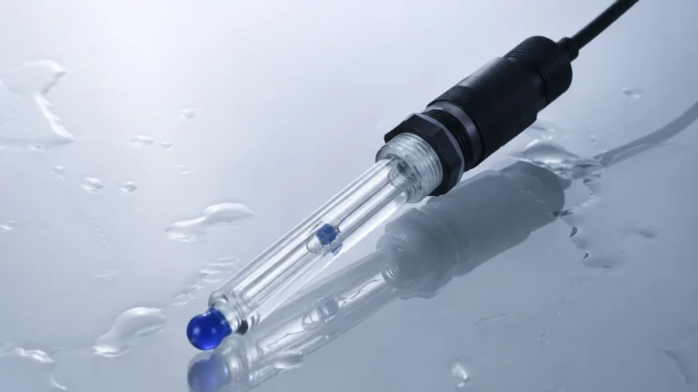
The core of an optical oxygen sensor is a sensing element (often a cap) coated with a luminophore—a chemical compound that fluoresces when exposed to specific wavelengths of light. The measurement process follows a structured sequence:
1. Excitation: The sensor emits a blue light (excitation light) from an internal LED. This light strikes the luminophore layer.
2. Energy Absorption: The molecules in the luminophore absorb the energy from the blue light and move to an excited electronic state.
3. Emission: As these molecules return to their ground state, they emit light at a longer wavelength, typically in the red spectrum (fluorescence).
4. Quenching: If oxygen molecules are present, they collide with the excited luminophore molecules and absorb their energy before they can emit red light. This process effectively "quenches" the fluorescence.
Phase Shift and Intensity
Modern industrial sensors typically measure the phase shift or the decay time of the luminescence rather than just the intensity. Because oxygen concentration is inversely proportional to the time the luminophore remains in an excited state, the sensor can calculate the partial pressure of oxygen with high precision. This method is inherently more stable than intensity-based measurements, which can be affected by LED degradation or turbidity in the liquid.
Optical vs. Electrochemical DO Sensors: A Comparative Analysis
For decades, the Clark cell (polarographic) and galvanic sensors were the industry standards. However, optical oxygen technology addresses several fundamental limitations of these older methods.
| Feature | Optical Oxygen Sensors | Electrochemical (Galvanic/Polarographic) |
| :— | :— | :— |
| Measurement Principle | Luminescence Quenching | Chemical Reduction of Oxygen |
| Flow Dependency | None (No oxygen consumption) | High (Requires constant flow) |
| Maintenance Frequency | Low (Cap change every 1-2 years) | High (Electrolyte/Membrane change monthly) |
| Warm-up Time | Instantaneous | 15 to 60 minutes |
| Interference | Minimal (H2S, CO2 do not interfere) | High (H2S, CO2, and pH levels) |
| Calibration Stability | High (Minimal drift) | Low (Frequent calibration required) |
| Initial Cost | Higher | Lower |
| Long-term TCO | Lower due to reduced labor | Higher due to frequent maintenance |
One of the most significant advantages of optical oxygen measurement is the lack of oxygen consumption. Because the sensor does not "consume" oxygen during the measurement, it does not require a minimum flow rate (typically 0.3 m/s for electrochemical sensors) to provide an accurate reading. This makes optical sensors ideal for stagnant water or low-flow applications.
Key Selection Criteria for Industrial Optical Oxygen Sensors
When selecting an optical oxygen sensor for industrial integration, engineers must evaluate several technical specifications to ensure compatibility with the process environment.
1. Measurement Range and Accuracy
Most industrial optical sensors cover a range from 0 to 20 mg/L (or 0 to 200% saturation). For specialized applications like boiler feedwater, "trace level" sensors are required, capable of measuring in the parts-per-billion (ppb) range. Accuracy is typically within ±1% of the reading or ±0.1 mg/L.
2. Temperature and Pressure Limits
Standard industrial probes are designed to operate between 0°C and 50°C. However, in chemical processes or Clean-in-Place (CIP) applications, sensors must withstand temperatures up to 130°C. Pressure ratings usually range from 2 bar to 10 bar. It is vital to confirm that the sensor housing (usually 316L stainless steel or PVC) can withstand the process pressure.
3. Signal Output and Integration
In the context of industrial automation, the sensor must communicate effectively with a PLC or DCS. Common outputs include:
* Analog: 4-20mA (Standard for most legacy systems).
* Digital: RS485 Modbus RTU or HART protocol.
* Wireless: Integration with LoRaWAN or NB-IoT for remote environmental monitoring.
For those looking to explore how these data points integrate into broader plant management systems, the Main Page of our technical resource site offers insights into the wider ecosystem of industrial measurement.
Installation and Engineering Considerations
Proper installation is paramount to ensuring the longevity and accuracy of an optical oxygen sensor. While optical technology is robust, it is not immune to physical and environmental factors.
Positioning in Tanks and Pipes
* Avoid Bubbles: In aeration basins, sensors should not be placed directly above air diffusers. Large bubbles striking the sensing cap can cause "noise" in the data and artificially high readings.
* Submersion Depth: Ensure the sensor is submerged deep enough to avoid the influence of surface air but high enough to avoid the sludge layer at the bottom of a tank.
* Orientation: Most sensors should be installed at an angle (e.g., 45 degrees) to prevent air bubbles from becoming trapped on the sensing surface.
Cleaning Systems
In "dirty" applications like wastewater treatment, biofouling is a major concern. Even though optical sensors do not have membranes, a layer of algae or slime on the sensing cap will block oxygen diffusion and slow the response time.
* Compressed Air Cleaning: Many industrial assemblies include a nozzle that blasts the sensor face with air at timed intervals.
* Mechanical Wipers: Some sensors use a motorized wiper to physically clear the sensing area.

Industrial Applications and Process Integration
Optical oxygen measurement is utilized across a diverse range of sectors, often working in tandem with level measurement to provide full process control.
Wastewater Treatment (Aeration Control)
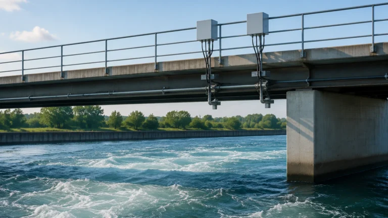
In the activated sludge process, microorganisms break down organic matter. This requires a precise amount of dissolved oxygen. If DO is too low, the microbes die; if it is too high, energy is wasted by the blowers. Optical sensors provide the real-time feedback loop necessary to modulate blower speed. Here, level sensors (such as ultrasonic or radar) are used to monitor the basin level, ensuring the DO sensors remain at the correct depth.
Power Plant Boiler Feedwater
Oxygen is a primary cause of corrosion in high-pressure boilers. Power plants use deaerators to remove oxygen, and optical sensors (specifically trace-level versions) monitor the efficiency of this process. Even a few ppb of oxygen can lead to catastrophic pipe failure over time.
Aquaculture
In fish farming, oxygen levels can drop rapidly due to high stocking densities. Optical sensors are preferred here because they require no flow, allowing them to be placed in quiet corners of a pond where fish might congregate. Their low maintenance requirement is also critical for remote sites where technical staff are not always present.
Limitations and Maintenance
While optical oxygen technology is superior in many ways, it has specific limitations:
1. Sensing Cap Lifespan: The luminophore layer eventually degrades due to exposure to high-intensity light and chemical abrasion. Most caps need replacement every 12 to 24 months.
2. Chemical Sensitivity: Certain organic solvents or strong oxidizing agents (like chlorine in high concentrations) can damage the sensing film.
3. Ambient Light Interference: While most modern sensors use optical filtering, extremely bright, direct sunlight hitting the sensor face in shallow water can occasionally interfere with the photodetector.
Calibration Procedures
Optical sensors are known for their "calibration stability," often holding their slope for several months. However, regular verification is still required. The most common method is the Air-Saturated Water calibration or the Water-Saturated Air calibration. Since the partial pressure of oxygen in the air is constant at a given barometric pressure and temperature, air calibration is a highly reliable and simple field method.
Frequently Asked Questions (FAQ)
Q: Does the turbidity of the water affect optical oxygen readings?
A: Generally, no. Because the sensor measures the phase shift of the light rather than just the intensity, suspended solids do not significantly impact the accuracy unless they physically coat the sensor cap.
Q: Can optical oxygen sensors be used in saltwater?
A: Yes, but salinity compensation is required. Oxygen solubility decreases as salinity increases. Most modern transmitters allow you to input the salinity value (in PSU or g/kg) to automatically correct the mg/L reading.
Q: How do I know when to replace the sensing cap?
A: Most industrial transmitters monitor the "diagnostic signal strength." When the fluorescence signal drops below a certain threshold, the system will trigger a maintenance alarm indicating the cap is nearing the end of its life.
Q: Is there a maximum cable length for these sensors?
A: If using an analog 4-20mA signal, the distance can be several hundred meters. If using digital RS485, distances up to 1,200 meters are possible without signal degradation, provided proper shielded cabling is used.
Conclusion
Optical oxygen technology represents a significant advancement in industrial liquid analysis. By eliminating the need for membranes, electrolytes, and constant flow, these sensors provide a reliable and cost-effective solution for long-term monitoring. For engineers and facility managers, the shift to optical measurement reduces labor costs and improves process stability.
When designing a system that requires both liquid analysis and physical level monitoring, it is essential to source instruments that are built for industrial rigors. Whether you are managing a wastewater facility or a chemical processing plant, selecting the right combination of sensors is the first step toward automation efficiency. To review product options and application support for your broader instrumentation needs, including level measurement, please visit our Main Page.