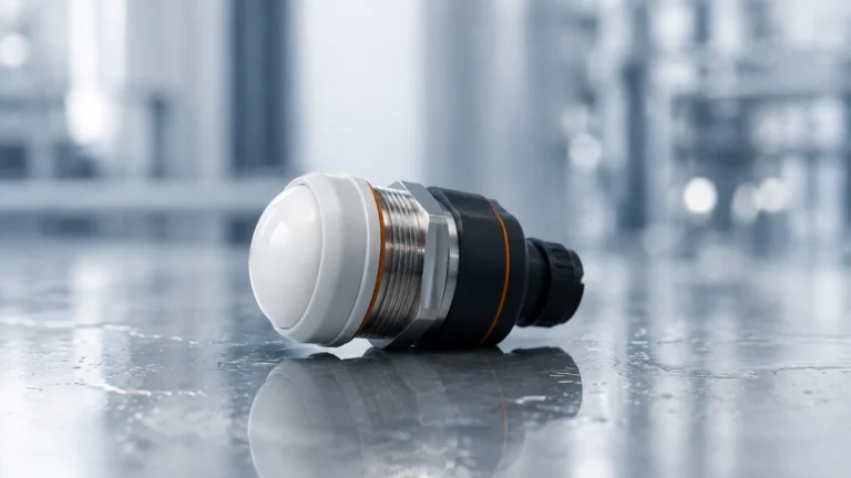
Ph Detector
Ph Detector
In industrial process control, the measurement of liquid properties is a multi-dimensional task. While level measurement ensures the quantity of a medium is known, analytical instrumentation, specifically the ph detector, provides critical data regarding the chemical state of that medium. For engineers managing water treatment, chemical processing, or oil and gas operations, the integration of reliable pH monitoring alongside level instrumentation is essential for safety, regulatory compliance, and process efficiency.
This guide examines the engineering principles behind pH detection, selection criteria for industrial environments, and the practical considerations for integrating these sensors into broader automated systems.
Fundamental Principles of pH Measurement
A ph detector operates on the principle of potentiometry. It measures the potential difference between two electrodes immersed in a solution: a sensing electrode (glass electrode) and a reference electrode. This potential is proportional to the hydrogen ion activity in the liquid, which defines its acidity or alkalinity.
The Nernst Equation
The relationship between the measured voltage and the pH value is governed by the Nernst Equation:
$$E = E_0 – \frac{2.303RT}{nF} \log(aH^+)$$
Where:
- E: Total potential measured (mV).
- E0: Standard potential of the electrode system.
- R: Gas constant.
- T: Absolute temperature (Kelvin).
- n: Charge of the ion (for H+, n=1).
- F: Faraday constant.
- aH+: Activity of hydrogen ions.
In practical terms, at 25°C (298.15 K), a change of one pH unit corresponds to a theoretical change of 59.16 mV. Because this voltage is highly dependent on temperature, modern industrial pH detectors always incorporate an Integrated Temperature Element (usually a Pt100 or Pt1000 RTD) to provide automatic temperature compensation (ATC).
The Glass Electrode Mechanism
The sensing portion of the ph detector is a thin, pH-sensitive glass membrane. When immersed, a hydrated gel layer forms on both the inside and outside of the glass. Hydrogen ions in the process liquid exchange with ions in the gel layer, creating a charge. The difference in charge between the inner hydrated layer (exposed to a stable internal buffer) and the outer layer (exposed to the process) generates the millivolt signal.
Component Architecture of an Industrial pH Detector
Industrial-grade pH sensors are designed to withstand harsher conditions than laboratory versions. A standard assembly typically includes:
1. Sensing Glass Bulb: Formulated for specific applications (e.g., high temperature, low conductivity, or hydrofluoric acid resistance).
2. Reference System: Usually a silver/silver chloride (Ag/AgCl) wire in a concentrated potassium chloride (KCl) electrolyte.
3. Junction: The physical interface where the reference electrolyte meets the process liquid. Common materials include ceramic, PTFE (Teflon), or wood.
4. Body Material: Often constructed from Ryton (PPS), PVDF, or Stainless Steel to ensure chemical compatibility.
5. Signal Converter: Since the high-impedance mV signal from the glass electrode is susceptible to noise, many modern detectors convert the signal to a 4-20mA, Modbus RTU, or HART protocol directly at the sensor head.
Selection Criteria for Industrial Applications
Choosing the right ph detector requires an analysis of the process environment. A sensor that works in a municipal water plant will likely fail within days in a chemical reactor.
Selection Table: Electrode Types and Applications
| Application Type | Membrane Glass Type | Junction Material | Typical Pressure/Temp Limits |
| :— | :— | :— | :— |
| General Water Treatment | Standard Green Glass | Ceramic | 6 bar / 80°C |
| Chemical Processing | High-Temp/High-pH Glass | PTFE (Teflon) | 10 bar / 110°C |
| Wastewater (High Solids) | Flat Surface Glass | Open Hole/Double Junction | 3 bar / 60°C |
| Pure Water (<20 µS/cm) | Low Impedance Glass | Refillable Liquid KCl | 0.5 bar / 50°C |
| HF Acid Environments | Antimony or HF Glass | Ceramic | 2 bar / 40°C |
Pressure and Flow Considerations
In pressurized pipelines, the reference electrolyte must be able to resist the process pressure to prevent the process liquid from entering the sensor (poisoning the reference). For high-pressure applications, sensors with pressurized gel reservoirs or solid-state electrolytes are preferred.
Installation and Mounting Guidelines
Correct installation is as vital as sensor selection. Improper mounting can lead to air pockets, electrode dehydration, or physical damage.
Mounting Orientations
* Angle of Installation: A ph detector should never be installed horizontally or upside down. It must be mounted at least 15° above the horizontal plane. This ensures that the internal filling solution stays in contact with the glass bulb and that any air bubbles inside the electrode rise to the top, away from the sensing tip.
* Submersion Mounting: Used in open tanks or basins. The sensor is attached to a mounting pipe (immersion sleeve) to protect the cable from the liquid.
* In-line (Flow-through) Mounting: The sensor is placed directly into a pipe via a T-fitting. The flow velocity should be controlled (typically < 2 m/s) to prevent "streaming potentials" or abrasive wear on the glass.
Cable Management
pH signals are extremely high impedance (often 100MΩ to 1000MΩ). Even a small amount of moisture in the connector or a nick in the cable can cause massive signal drift. It is recommended to use pre-assembled, shielded cables and avoid splicing whenever possible.
Maintenance and Calibration Protocols
Unlike a radar level meter, which may operate for years without contact, a ph detector is a consumable item that interacts chemically with its environment. Regular maintenance is non-negotiable.
Calibration Cycles
Calibration should be performed using at least two buffer solutions (typically pH 4.0, 7.0, or 10.0).
1. Zero Point Calibration: Usually done at pH 7.0.
2. Slope Calibration: Done at pH 4.0 or 10.0 to determine the efficiency of the electrode.
An electrode is generally considered at the end of its life when the slope drops below 85% or the zero-point offset exceeds ±30mV.
Cleaning Procedures
* Bio-fouling: Use a 5-10% hydrochloric acid (HCl) soak for 15 minutes.
* Oils and Greases: Use a mild detergent or isopropyl alcohol.
* Inorganic Scale: Use a 5% EDTA solution or dilute acid.

Integration with Level Measurement Systems
In industrial automation, the ph detector often works in tandem with level measurement instruments. For instance, in a neutralization tank, an ultrasonic or radar level sensor (such as those found on the Main Page of specialized instrument providers) monitors the volume of the tank to prevent overfills, while the pH sensor controls the dosing pumps for acid or caustic reagents.
By integrating these two data points into a single PLC (Programmable Logic Controller), operators can calculate the mass balance of chemicals required for treatment. For example, if the level in a tank is rising rapidly, the dosing rate may need to be adjusted proportionally to the pH change to maintain a stable effluent quality.
Limitations and Common Risks
* Electrode Poisoning: Heavy metals (like mercury or lead) or sulfides can react with the silver ions in the reference electrolyte, clogging the junction.
* Dehydration: If a pH bulb dries out, the hydrated gel layer collapses. While some sensors can be regenerated by soaking in KCl solution, permanent damage often occurs.
* Ground Loops: In metal tanks or pipes, stray electrical currents can interfere with the low-voltage pH signal. Using a transmitter with a solution ground or an isolated output is the standard engineering fix.
Frequently Asked Questions (FAQs)
Q: How long does a typical industrial pH sensor last?
A: In clean water applications, a sensor may last 12 to 24 months. In harsh chemical processes or high temperatures, the lifespan may be reduced to 3 to 6 months.
Q: Can I use a pH detector to measure the pH of oil?
A: pH is a measurement of hydrogen ion activity in aqueous (water-based) solutions. It cannot be measured directly in pure oils. However, it can be measured in water-oil emulsions or by extracting the acid into a water phase.
Q: Why does my pH reading drift after calibration?
A: Drift is often caused by a clogged junction or temperature fluctuations. Ensure the sensor has reached thermal equilibrium with the process before taking a final reading.
Q: Does the flow rate affect pH readings?
A: Yes. High flow rates can cause pressure variations at the junction, leading to unstable readings. Conversely, very low flow in stagnant areas may not provide a representative sample of the process.
Conclusion
The ph detector is a sophisticated electrochemical tool that requires careful selection and proactive maintenance. By understanding the Nernstian principles and the physical limitations of glass electrodes, engineers can implement robust monitoring solutions. When paired with reliable level measurement technologies—such as those available at Welk—industrial operators can achieve comprehensive control over their liquid processes, ensuring both the quantity and quality of their media are precisely managed.