Expansion Vessels for Solar
Expansion Vessels for Solar
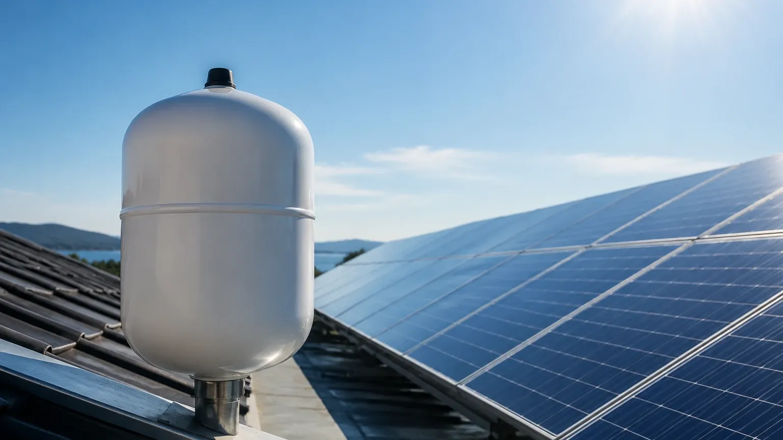
In solar thermal systems, managing the volumetric expansion of heat transfer fluids is a critical safety and operational requirement. Unlike standard domestic heating systems, solar thermal circuits are subject to extreme temperature fluctuations, ranging from sub-zero winter nights to high-temperature stagnation states exceeding 160°C. Expansion vessels for solar are specialized pressure vessels designed to accommodate these changes, ensuring the system remains pressurized and preventing the loss of expensive glycol-based fluids through safety relief valves.
This guide examines the technical principles, selection criteria, and installation requirements for solar expansion vessels, providing engineers and system designers with a factual reference for maintaining system integrity.
Measurement and Operational Principles
The fundamental principle behind expansion vessels for solar is Boyle’s Law, which describes the inversely proportional relationship between the absolute pressure and volume of a gas at a constant temperature. In a closed-loop solar circuit, the heat transfer fluid (typically a mixture of water and propylene glycol) is incompressible. As the solar collectors absorb energy, the fluid temperature rises, causing it to expand.
The Membrane Mechanism
An expansion vessel is divided into two chambers by a flexible diaphragm or membrane. One side is pre-charged with an inert gas (usually nitrogen to prevent internal corrosion), while the other side is connected to the solar circuit.
1. Cold State: When the system is at its lowest operating temperature, the nitrogen pre-charge occupies most of the vessel’s volume, pressing the membrane against the inlet.
2. Expansion Phase: As the fluid heats up and expands, the increasing pressure forces the fluid into the vessel, compressing the nitrogen cushion. This prevents a rapid spike in system pressure.
3. Contraction Phase: When the fluid cools, the compressed gas pushes the fluid back into the circuit, maintaining a minimum operating pressure and preventing vacuum formation or cavitation in the circulation pump.
Solar-Specific Requirements
Standard heating expansion vessels are often unsuitable for solar applications. Solar-rated vessels must utilize membranes capable of withstanding higher continuous temperatures and chemical exposure to glycols. Furthermore, they must be sized to handle "stagnation," a condition where the pump stops (due to power failure or a full storage tank) and the fluid in the collectors turns to steam. The expansion vessel must be large enough to accommodate the displaced liquid as steam forms in the collector array.
Key Evaluation Criteria for Selection
When specifying expansion vessels for solar, engineers must evaluate several technical parameters to ensure long-term reliability. For broader system integration and high-precision monitoring of these industrial processes, engineers often consult the Main Page of specialized instrument manufacturers to source compatible level and pressure sensors.
1. Temperature Rating
Solar vessels are typically rated for peak temperatures of 120°C to 130°C at the membrane, though the system fluid may be hotter. If the vessel is installed close to the collector array, an intermediate "cooling vessel" or "heat sink" may be required to protect the membrane from thermal degradation.
2. Pressure Limits
The maximum working pressure (MWP) must exceed the safety valve setting of the solar station. Most industrial solar vessels are rated for 6 bar or 10 bar. The pre-charge pressure must be accurately set during installation based on the static height of the system.
3. Material Compatibility
The membrane must be made of high-grade elastomers like EPDM (Ethylene Propylene Diene Monomer) or Butyl, which are resistant to the corrosive effects of concentrated glycol and high-temperature water mixtures.
Practical Selection Table
The following table provides a general guideline for sizing expansion vessels for solar based on collector area and system volume. Note that these are estimates; precise calculations must account for the expansion coefficient of the specific glycol percentage used.
| Collector Area (m²) | Total System Volume (L) | Recommended Vessel Size (L) | Typical Pre-charge (bar) |
| :— | :— | :— | :— |
| 2 – 5 | 20 – 40 | 18 – 25 | 1.5 – 2.5 |
| 6 – 10 | 50 – 80 | 35 – 50 | 2.0 – 3.0 |
| 11 – 20 | 100 – 160 | 80 – 100 | 2.5 – 3.5 |
| 21 – 50 | 200 – 450 | 150 – 250 | 3.0 – 4.5 |
| 50+ | > 500 | Custom Multi-Vessel Array | Site Specific |
Sizing Calculations
To calculate the required nominal volume ($V_n$) of an expansion vessel, the following formula is used:
$$V_n = \frac{V_e + V_v}{K}$$
Where:
* $V_e$ (Expansion Volume): The volume of fluid expansion from the minimum to maximum temperature. For a 40% glycol mix, this is approximately 7-9% of the total system volume.
* $V_v$ (Water Reserve): A safety margin (usually 0.5% of total volume or 3 liters, whichever is greater) to ensure fluid remains in the vessel even when cold.
* $K$ (Pressure Factor): Calculated as $\frac{P_e – P_0}{P_e + 1}$, where $P_e$ is the maximum operating pressure (safety valve minus 10%) and $P_0$ is the pre-charge pressure.
In solar systems, $V_e$ must also include the volume of the collectors if stagnation is expected, as the entire collector volume will be displaced into the vessel by steam.
Installation Considerations
Proper installation is as critical as sizing. Incorrect placement can lead to premature membrane failure or system airlocks.
1. Orientation: Most manufacturers recommend installing the vessel with the water connection facing upwards or downwards depending on the internal membrane design. Downward connections help prevent air from being trapped in the vessel.
2. Location: The vessel should be installed on the suction side of the pump to maintain positive pressure at the pump inlet, preventing cavitation. It must be placed before the check valve in the return line.
3. Pre-charge Adjustment: The nitrogen pre-charge must be set before the vessel is connected to the system or while the system is unpressurized. The pre-charge should typically be 0.2 to 0.3 bar below the static pressure of the system at the vessel’s location.
4. Isolation and Maintenance: A lockable isolation valve (cap valve) should be installed to allow for the vessel to be disconnected for pressure checks without draining the entire solar circuit.
Integration with Level and Pressure Monitoring
In large-scale industrial solar thermal plants, expansion vessels for solar are part of a complex fluid management system. While the vessel handles physical expansion, level measurement instruments play a vital role in system health monitoring.
For instance, hydrostatic level transmitters can be used in larger atmospheric buffer tanks that work in tandem with pressurized expansion vessels. If a system experiences a leak, the pressure will drop, but the level in the storage tanks may also fluctuate unexpectedly. By utilizing radar or ultrasonic level sensors, operators can distinguish between normal thermal expansion and actual fluid loss. For detailed specifications on level measurement technology suitable for high-temperature industrial environments, engineers can review product options and application support on the Main Page of industrial instrumentation providers.
Limitations and Common Risks
Membrane Permeability
Over time, nitrogen can permeate through the membrane into the fluid, or air can migrate into the gas chamber. This leads to a loss of pre-charge pressure. When pre-charge is lost, the vessel fills with fluid, leaving no room for expansion, which causes the safety valve to lift during the next heating cycle.
Stagnation Fatigue
Frequent stagnation cycles subject the vessel to rapid pressure and temperature spikes. If the vessel is undersized, the safety valve will discharge glycol. Since solar systems are often on roofs, this loss of fluid may go unnoticed until the pump fails to circulate due to low pressure.
Corrosion
If air (oxygen) enters the system due to a failed expansion vessel or improper venting, it reacts with the glycol to form organic acids. These acids lower the pH of the fluid, leading to rapid corrosion of the expansion vessel's steel shell and other metallic components.
Maintenance Checklist
To ensure the longevity of expansion vessels for solar, the following maintenance steps should be performed annually:
* Pressure Verification: Check the gas pre-charge pressure using a calibrated gauge. This must be done with the vessel isolated from the system pressure.
* Visual Inspection: Check for signs of external corrosion, especially around the threaded connections.
* Fluid Analysis: Check the pH and concentration of the glycol. Acidic fluid can damage the internal diaphragm.
* Safety Valve Test: Ensure the safety valve is not leaking, which often indicates the expansion vessel has reached its limit or failed.
Frequently Asked Questions (FAQs)
Q: Can I use a standard potable water expansion vessel for a solar system?
A: No. Potable water vessels are designed for lower temperatures and may not be compatible with glycol. Solar-specific vessels have specialized membranes and higher temperature ratings.
Q: Why does my solar system pressure drop at night?
A: This is normal thermal contraction. However, if the pressure drops to zero, the expansion vessel pre-charge may be too high, or there may be a leak in the system.
Q: How long do solar expansion vessels typically last?
A: In a well-maintained system with proper sizing and stagnation control, a high-quality vessel can last 10 to 15 years. Membrane failure is the most common end-of-life event.
Q: What is the purpose of an intermediate vessel?
A: An intermediate vessel (or cooling vessel) is an uninsulated tank placed between the solar circuit and the expansion vessel. It allows the hot fluid to cool down before it reaches the expansion vessel's membrane, extending the membrane's lifespan.
By understanding the mechanical requirements and calculation methods for expansion vessels for solar, engineers can design more resilient renewable energy systems. For those managing complex industrial automation and requiring precise fluid monitoring, visiting the Main Page provides access to the necessary level measurement tools to complement these pressure management components.