Potentiometric Sensors
Potentiometric Sensors
In the landscape of industrial level measurement, potentiometric sensors represent a specialized and highly effective technology, particularly within the food, beverage, and pharmaceutical sectors. Unlike traditional float switches or complex non-contact systems, potentiometric sensors utilize the electrical properties of the process medium to determine level with high precision. This guide provides a comprehensive technical overview of the measurement principles, application criteria, and installation requirements for engineers and project managers evaluating these instruments.
Understanding the Measurement Principle of Potentiometric Sensors
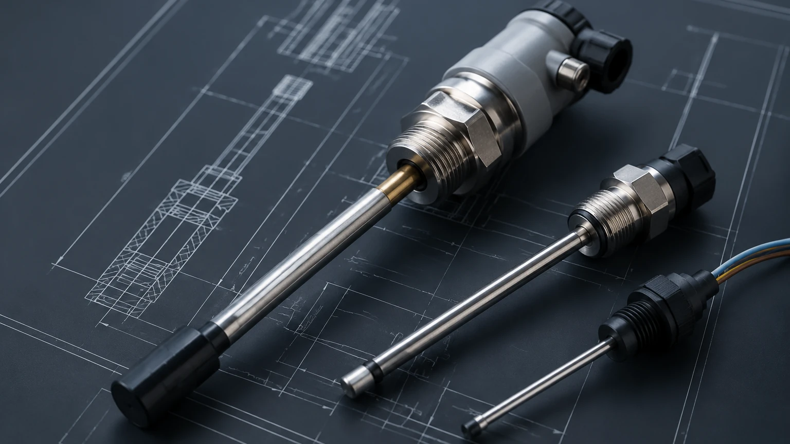
The operation of potentiometric sensors is based on the principle of a voltage divider. The sensor typically consists of a metallic probe (the measuring electrode) that is partially submerged in a conductive liquid. A low-voltage alternating current is applied to the probe, creating a defined voltage drop along its length.
When the probe comes into contact with a conductive medium, the liquid acts as a "wiper" in a potentiometer circuit. The liquid effectively shorts the probe to the tank wall (or a reference electrode), and the sensor measures the ratio of the voltage drop from the top of the probe to the liquid surface against the total voltage. Because the resistance of the probe is uniform, the measured voltage is directly proportional to the filling level.
Mathematically, if $V_{total}$ is the applied voltage and $L$ is the total length of the probe, the voltage $V_x$ at a level $x$ can be expressed as:
$$V_x = V_{total} \cdot (x / L)$$
One of the most significant advantages of this principle is its independence from the physical properties of the medium, such as density, temperature, or pressure. As long as the medium meets a minimum conductivity threshold—typically >1 µS/cm—the measurement remains accurate and stable. This makes it a robust alternative to hydrostatic pressure sensors, which are sensitive to density changes, or ultrasonic sensors, which can be affected by foam or vapor layers.
Key Advantages in Industrial Level Measurement
Potentiometric sensors are frequently selected for applications where other technologies struggle. Their design is inherently hygienic, making them a staple in sanitary processing. For a comprehensive look at how these integrate with other measurement technologies, you can visit the Main Page for detailed product specifications.
Resistance to Buildup and Foam
One of the primary challenges in level sensing is the presence of foam or viscous residue on the probe. Many capacitive sensors or ultrasonic devices may misinterpret foam as the actual liquid level. Potentiometric sensors, however, are largely unaffected by foam because the measurement circuit requires a low-impedance connection provided by the bulk liquid. Similarly, because the measurement relies on a voltage ratio rather than absolute resistance, thin films of buildup on the probe do not significantly shift the measurement result.
High Precision in Small Tanks
In small processing vessels or mixing tanks, radar and ultrasonic sensors often face "dead zones" or interference from internal structures like agitators. Potentiometric probes can measure right up to the process connection, offering a nearly zero-distance dead zone. This allows for maximum utilization of the tank volume.
Rapid Response Time
Because the measurement is purely electrical and does not rely on signal processing of reflected waves or mechanical movement, the response time is nearly instantaneous. This is critical in high-speed filling applications or processes with rapid level fluctuations.
Technical Selection Criteria and Comparison
When selecting a level measurement technology, it is essential to compare the performance characteristics against the specific needs of the application. The following table compares potentiometric sensors with other common industrial level measurement technologies.
Selection Table: Level Measurement Technology Comparison
| Feature | Potentiometric Sensors | Radar Level Meters | Ultrasonic Sensors | Hydrostatic Transmitters |
| :— | :— | :— | :— | :— |
| Measurement Type | Contact | Non-contact | Non-contact | Contact (Pressure) |
| Min. Conductivity | >1 µS/cm | N/A | N/A | N/A |
| Effect of Density | None | None | None | High |
| Effect of Foam | Low | Moderate | High | None |
| Dead Zone | Minimal (0-20 mm) | 50-300 mm | 100-500 mm | None |
| Max Temperature | Up to 140°C | Up to 450°C | Up to 80°C | Up to 100°C |
| Installation | Top-mounted | Top-mounted | Top-mounted | Bottom/Side-mounted |
Application Suitability
* Ideal for: Milk, yogurt, fruit juices, cleaning agents (CIP solutions), and sauces.
* Suitable for: Deionized water (with specific high-sensitivity models) and chemical acids.
* Unsuitable for: Non-conductive oils, fuels, or dry bulk solids.
Installation Guidelines for Optimal Performance
Proper installation is critical to ensure the accuracy and longevity of potentiometric sensors. Engineers should adhere to the following checklist during the design and commissioning phases:
1. Grounding and Reference: The measurement principle requires a return path for the current. In metallic tanks, the tank wall serves as the reference ground. If the tank is made of plastic or glass (non-conductive), a reference electrode must be installed or a sensor with a dual-probe design must be used.
2. Probe Length and Positioning: Probes are typically available in lengths from 200 mm to 3000 mm. The probe should be installed vertically. If horizontal installation is necessary (e.g., for point level detection), the probe must be angled slightly to ensure the liquid drains off the tip, preventing "bridging."
3. Process Connections: For hygienic applications, use G1/2" or G1" threads with appropriate O-rings (EPDM or FKM) that meet FDA requirements. Ensure the welding sleeve is flush with the tank interior to prevent bacterial growth zones.
4. Agitator Clearance: While potentiometric sensors are less sensitive to turbulence than ultrasonic sensors, the probe should be positioned at a distance from agitator blades to avoid mechanical stress or damage. In high-viscosity media with heavy agitation, a reinforced probe or a stilling well may be required.
5. Electrical Connection: Use shielded cables to prevent electromagnetic interference (EMI) from nearby high-power motors or frequency converters. The 4-20 mA output signal is standard, but many modern sensors also support IO-Link for digital parameterization and diagnostics.
Limitations and Common Operational Risks
While highly versatile, potentiometric sensors are not a universal solution. Project teams must be aware of specific limitations to avoid measurement failures.
Conductivity Requirements
The most common failure mode is attempting to use a potentiometric sensor in a non-conductive medium. Pure oils, hydrocarbons, and highly purified demineralized water (below 1 µS/cm) will not provide the necessary electrical path, resulting in an "empty tank" error or erratic readings.
Coating and Bridging
Although the technology is resistant to thin films, extremely thick, non-conductive coatings (such as heavy fats or waxes) can insulate the probe from the liquid. If the medium is prone to hardening or crystallizing on the probe surface, regular Cleaning-in-Place (CIP) cycles are necessary to maintain accuracy.
Mechanical Stress
Long probes in agitated tanks are subject to bending moments. If the probe exceeds 1500 mm in a high-flow environment, it should be supported at the bottom or the diameter of the probe should be increased to improve structural rigidity.
Maintenance and Calibration
One of the benefits of potentiometric sensors is their low maintenance requirement. Since there are no moving parts, mechanical wear is non-existent. However, periodic verification is recommended:
* Visual Inspection: During tank cleaning, inspect the probe for signs of pitting, corrosion, or permanent deformation.
* Zero-Point Check: Ensure the sensor reads 4 mA (or the equivalent digital value) when the tank is empty. If the sensor is installed in a plastic tank, verify the integrity of the grounding strap or reference electrode.
* Conductivity Verification: If the process medium changes, verify that the new liquid meets the minimum conductivity requirements of the sensor.
Frequently Asked Questions (FAQs)
Q: Can potentiometric sensors be used in pressurized vessels?
A: Yes, most industrial potentiometric sensors are designed to withstand pressures up to 16 bar (approx. 232 psi), with some specialized models rated higher. Always check the process connection specifications.
Q: Does the temperature of the liquid affect the accuracy?
A: The potentiometric principle is largely independent of temperature. However, the electronics in the sensor head usually have an operating limit (typically up to 70°C or 85°C). For high-temperature processes like steam sterilization (SIP) at 140°C, sensors with cooling necks or remote electronics should be used.
Q: How does this technology handle turbulent surfaces?
A: Potentiometric sensors are excellent for turbulent surfaces. Because the measurement is an instantaneous electrical ratio, it can be electronically damped (smoothed) within the sensor's firmware to provide a stable output even if the liquid is splashing.
Q: Is it possible to cut the probe to length in the field?
A: Some models allow for field-shortening of the probe. However, this usually requires a recalibration of the electronics to the new total length. It is generally recommended to order the exact length required for the application.
Conclusion and Project Confirmation
Before proceeding with the procurement of potentiometric sensors, project engineers should confirm the following data points:
* Minimum Conductivity: Confirm the liquid is >1 µS/cm.
* Tank Material: Ensure a proper ground reference is available.
* Media Characteristics: Identify if the medium is prone to heavy, insulating coatings.
* Vessel Geometry: Determine the required probe length and the presence of internal obstructions.
By selecting the correct sensor configuration and following standardized installation practices, potentiometric sensors provide a reliable, maintenance-free solution for demanding liquid level applications. For further assistance in selecting the right instrumentation for your specific industrial environment, Review product options and application support to ensure your system meets all technical and regulatory requirements.