Orp Sensor
Orp Sensor
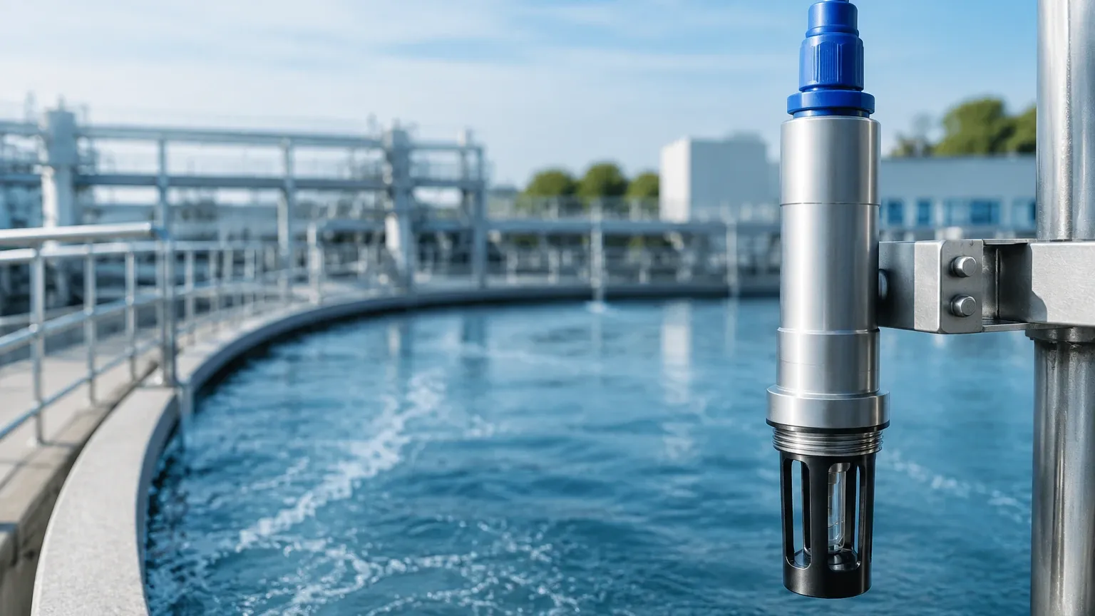
In industrial process control and water quality monitoring, the orp sensor—also known as a Redox (Reduction-Oxidation) sensor—is a fundamental instrument used to measure the chemical activity of a solution. While level measurement technologies such as radar and ultrasonic sensors track the quantity of a medium, ORP sensors provide critical data regarding the chemical state of that medium. Understanding the technical nuances of ORP measurement is essential for engineers designing automated dosing systems, wastewater treatment plants, and chemical manufacturing processes.
Measurement Principles of ORP Sensors
Oxidation-Reduction Potential (ORP) is a measurement of the tendency of a chemical species to acquire electrons and thereby be reduced. It is measured in millivolts (mV). A positive ORP reading indicates an oxidizing environment (where the solution tends to gain electrons), while a negative reading indicates a reducing environment (where the solution tends to lose electrons).
The Electrochemical Cell
An orp sensor operates as an electrochemical cell. It typically consists of two primary components: a measuring electrode and a reference electrode.
1. Measuring Electrode: This is usually made from a noble metal, most commonly platinum, though gold is used in specific applications like cyanide oxidation. The noble metal acts as a surface for electron exchange without reacting chemically with the solution itself.
2. Reference Electrode: This electrode provides a stable, constant electrochemical potential against which the measuring electrode is compared. The most common reference system is the Silver/Silver Chloride (Ag/AgCl) electrode, immersed in a potassium chloride (KCl) electrolyte.
The Nernst Equation
The potential generated at the measuring electrode follows the Nernst Equation, which relates the measured voltage to the ratio of oxidized to reduced species in the liquid. When these two electrodes are immersed in a solution, a voltage is generated that is proportional to the ORP of the liquid. This millivolt signal is then transmitted to a controller or transmitter for display and process logic execution.
Industrial Applications and Selection Criteria
Selecting the correct orp sensor requires a deep understanding of the process environment. Unlike level meters that can often be mounted non-contact, ORP sensors are typically in direct contact with the process fluid, making material compatibility and sensor design paramount.
Key Application Areas
* Wastewater Treatment: Monitoring the destruction of chromates or the oxidation of cyanides. It is also used to manage the nitrification and denitrification processes.
* Disinfection Control: In cooling towers and swimming pools, ORP is a direct indicator of the effectiveness of chlorine or ozone as a biocide.
* Chemical Manufacturing: Controlling batch reactions where a specific redox state must be maintained to ensure product quality and safety.
* Mining: Used in ore flotation and leaching processes to optimize chemical consumption.
Selection Table: ORP Sensor Types
| Sensor Feature | Standard Industrial | Heavy-Duty / Slurry | High-Temperature/Pressure |
| :— | :— | :— | :— |
| Electrode Material | Platinum | Platinum (Flat Surface) | Platinum |
| Reference Junction | Single Junction (PTFE) | Double/Triple Junction | Pressurized Reference |
| Body Material | Ryton (PPS) or Epoxy | PVDF or Stainless Steel | Glass or Stainless Steel |
| Max Temperature | 60°C to 80°C | 0°C to 100°C | Up to 130°C |
| Max Pressure | 6 bar (87 psi) | 7 bar (100 psi) | 10+ bar (145+ psi) |
| Common Use | Water treatment | Pulp & Paper, Mining | Chemical Reactors, CIP |
Technical Considerations for Sensor Design
When evaluating an orp sensor, engineers must consider the junction type and the electrolyte style. The junction is the point where the internal reference electrolyte meets the process fluid.
* Single vs. Double Junction: In processes containing heavy metals, proteins, or sulfides, a single junction sensor is prone to "poisoning," where the process ions react with the silver ions in the reference electrolyte, clogging the junction. A double junction design adds an extra chamber to protect the reference element, significantly extending the sensor's lifespan in harsh environments.
* Flat Surface vs. Bulb: For applications with high solids or fibrous materials (like paper pulp), a flat-surface sensor is preferred. The flow of the liquid across the flat surface creates a self-cleaning effect, preventing the accumulation of debris that would otherwise coat a traditional bulb-shaped electrode.
Installation Guidelines
Proper installation is critical to ensure the accuracy and longevity of an orp sensor. Because these sensors rely on electrochemical reactions, they are sensitive to flow dynamics and physical positioning.
1. Orientation: Sensors should never be installed horizontally or upside down. A minimum angle of 15° above the horizontal is required to ensure that the internal electrolyte stays in contact with the pH/ORP bulb and that air bubbles do not trap themselves in the sensing tip.
2. Submersion: The sensor must remain fully submerged at all times. If the sensor dries out, the reference junction can crystallize, leading to permanent damage or sluggish response times. In tanks where levels fluctuate, integrating the sensor with reliable level measurement solutions found on the Main Page ensures that dosing only occurs when the sensor is properly immersed.
3. Flow Velocity: While some flow is necessary to provide a representative sample to the electrode, excessive velocity can cause "streaming potentials" (static interference) or physical erosion of the platinum tip. Ideally, flow should be between 0.5 and 2 meters per second.
4. Cable Management: ORP signals are high-impedance millivolt signals. Cables should be kept as short as possible and routed away from high-voltage power lines or variable frequency drives (VFDs) to prevent electromagnetic interference.
Maintenance, Calibration, and Troubleshooting
An orp sensor is a consumable item; its sensitivity will naturally degrade over time due to electrode coating or electrolyte depletion.
Cleaning Protocols
If the sensor response becomes sluggish, cleaning is the first step.
* Oily/Greasy Coatings: Use a mild detergent or isopropyl alcohol.
* Mineral Scales (Calcium): Use a 5% Hydrochloric Acid (HCl) soak for 5–10 minutes.
* Biological Growth: Use a dilute bleach solution.
Calibration (Verification)
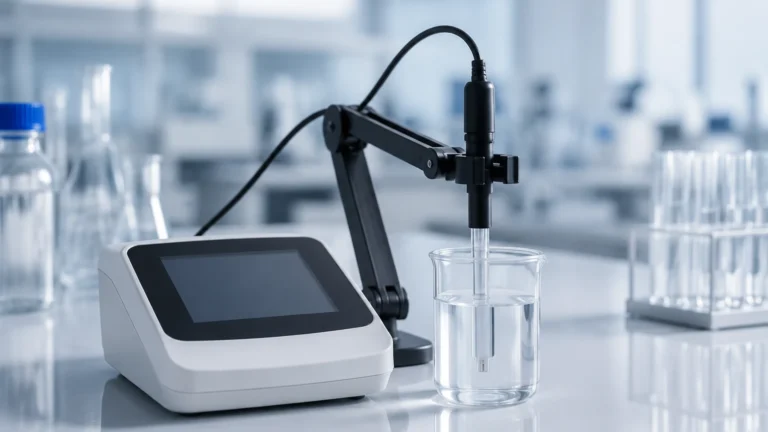
Unlike pH sensors, ORP sensors are technically "verified" rather than calibrated in the traditional sense, as the mV output of the platinum/reference pair is a physical constant. Verification is performed using Quinhydrone solutions or commercially available Redox standards (e.g., 200mV or 475mV). If the sensor reading deviates by more than ±20mV from the standard, it typically indicates the sensor needs cleaning or replacement.
Limitations of ORP Measurement
While powerful, the orp sensor has specific limitations that engineers must account for in process design:
* Non-Specificity: ORP measures the total redox potential of a solution. It cannot distinguish between different oxidizing agents. For example, it cannot tell the difference between chlorine and ozone; it only measures the total oxidizing "strength."
* pH Dependency: In many chemical reactions, the ORP value is heavily influenced by the pH of the solution. If the pH fluctuates significantly, the ORP reading may change even if the concentration of the oxidizer remains constant.
* Temperature Sensitivity: Although ORP is less temperature-dependent than pH, temperature still affects the activity of ions and the reference electrode potential. High-quality transmitters should offer temperature compensation.
Integration with Industrial Automation
In modern B2B environments, an orp sensor rarely operates in isolation. It is typically part of a larger control loop. For instance, in a cooling tower water treatment system, the ORP sensor triggers a chemical feed pump to add biocide. To prevent the pump from running dry or dosing into an empty pipe, the system must be interlocked with level transmitters and flow switches.
By combining precise chemical analysis from an orp sensor with the robust level monitoring hardware available at the Main Page, facilities can achieve a high degree of automation, reducing chemical waste and ensuring environmental compliance.
Frequently Asked Questions (FAQs)
Q: How long does an industrial ORP sensor typically last?
A: In clean water applications, a sensor may last 1–2 years. In harsh chemical processes or high-temperature environments, the lifespan may be reduced to 3–6 months.
Q: Can I use a pH meter to read an ORP sensor?
A: Most modern pH meters have a "millivolt mode" that can display the raw signal from an ORP sensor. However, specialized ORP controllers are recommended for process control to handle specific setpoints and dosing logic.
Q: Why is my ORP reading drifting?
A: Drifting is often caused by a contaminated reference junction or a coated platinum tip. It can also be caused by ground loops if the sensor is not properly isolated from the tank's electrical potential.
Q: Does the size of the platinum tip matter?
A: A larger platinum surface area generally provides a more stable and faster response in solutions with low redox activity, but it is also more susceptible to physical coating.
By adhering to these engineering principles and selection guidelines, B2B procurement and technical teams can ensure the reliable performance of their liquid analysis systems, maintaining process safety and efficiency across various industrial sectors.