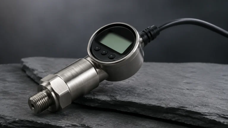
Pressure and Temperature Transmitter
Pressure and Temperature Transmitter
In modern industrial process control, the integration of multiple sensing capabilities into a single device has become a standard for efficiency and accuracy. A pressure and temperature transmitter, often referred to in engineering circles as a multivariable transmitter, is designed to measure both the static or differential pressure and the process temperature simultaneously. This dual-functionality is particularly critical in applications where fluid density varies with temperature, such as in hydrostatic level measurement, steam flow monitoring, and complex chemical reactions.
For engineers and plant managers, understanding the underlying physics and the mechanical constraints of these instruments is essential for maintaining system integrity. By consolidating sensors, facilities can reduce the number of process penetrations, minimize potential leak points, and simplify the wiring architecture of the control loop.
Measurement Principles and Technology
To effectively select and deploy a pressure and temperature transmitter, one must first understand how these two distinct physical properties are captured and converted into a standardized electronic signal.
Pressure Measurement Principles
Most industrial transmitters utilize one of two primary sensing technologies for pressure:
1. Piezoresistive Sensors: These sensors consist of a diaphragm with strain gauges diffused into a silicon or ceramic substrate. When process pressure deforms the diaphragm, the electrical resistance changes proportionally. This change is measured via a Wheatstone bridge circuit. Piezoresistive sensors are highly sensitive and suitable for a wide range of pressures, from low-vacuum to high-pressure hydraulic systems.
2. Capacitive Sensors: In this design, a sensing diaphragm is positioned between two fixed capacitor plates. Pressure shifts the diaphragm, changing the capacitance between it and the plates. This technology is known for its excellent long-term stability and resistance to overpressure conditions, making it a preferred choice for critical safety loops.
Temperature Measurement Principles
Temperature sensing within a multivariable transmitter is typically achieved through one of the following:
* Resistance Temperature Detectors (RTDs): Usually a Pt100 or Pt1000 platinum element. As temperature increases, the electrical resistance of the metal increases in a highly linear and predictable manner. RTDs are favored for their high accuracy and repeatability over a range of -200°C to 650°C (-328°F to 1202°F).
* Thermocouples: These consist of two dissimilar metals joined at one end. A temperature gradient across the metals produces a small voltage (the Seebeck effect). While less linear than RTDs, thermocouples are used for extreme high-temperature applications exceeding 1000°C (1832°F).
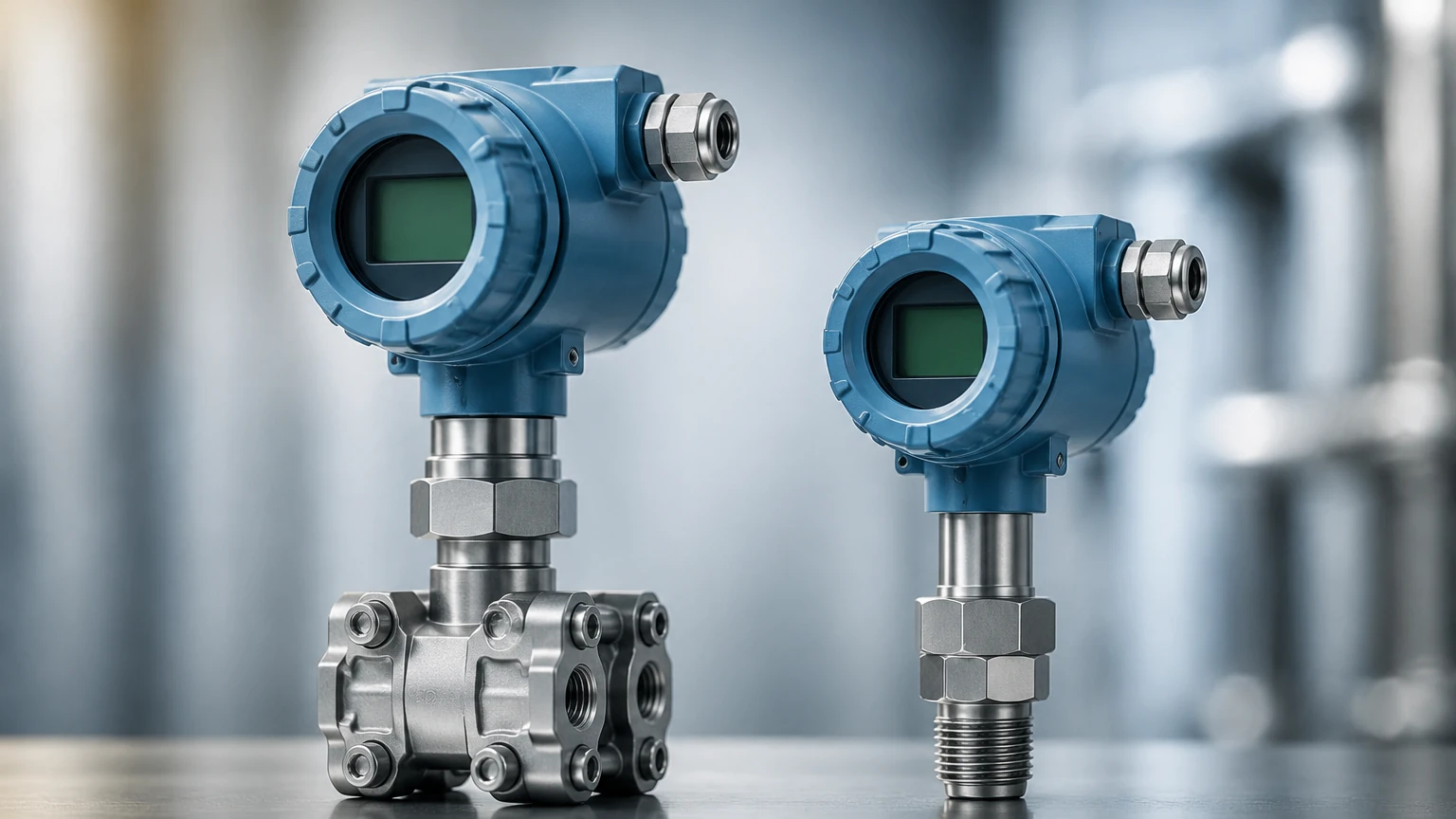
In a combined pressure and temperature transmitter, the temperature sensor may be integrated directly into the pressure cell or provided as an external probe (thermowell) connected to the transmitter electronics to ensure the electronics are not compromised by extreme process heat.
The Role of Temperature in Level Measurement
One of the primary reasons for integrating temperature sensing into a pressure transmitter is to improve the accuracy of hydrostatic level measurement. The fundamental formula for hydrostatic level is:
P = ρ × g × h
Where:
* P is the hydrostatic pressure.
* ρ (Rho) is the density of the liquid.
* g is the gravitational constant.
* h is the height (level) of the liquid.
In industrial environments, the density (ρ) of a liquid is not constant; it changes as the temperature fluctuates. For example, as water or oil heats up, it expands and its density decreases. If a transmitter only measures pressure without accounting for temperature, the calculated level (h) will be incorrect. A multivariable transmitter provides the real-time temperature data required for the control system to perform "density compensation," ensuring the reported level remains accurate regardless of thermal cycles.
For a comprehensive overview of how these sensors integrate into broader automation systems, engineers can consult the Main Page for technical specifications and instrument compatibility.
Technical Selection Criteria
Selecting the correct pressure and temperature transmitter requires a detailed analysis of the process media and environmental conditions. The following table provides a comparison of key specifications found in industrial-grade units.
| Specification | Industrial Standard | High-Precision / Oil & Gas |
| :— | :— | :— |
| Pressure Range | 0–100 bar (0–1450 psi) | 0–700+ bar (0–10,000+ psi) |
| Temperature Range | -40°C to 120°C | -60°C to 450°C+ |
| Accuracy (Pressure) | ±0.1% of span | ±0.04% to ±0.075% of span |
| Accuracy (Temp) | ±0.5°C | ±0.1°C to ±0.2°C |
| Output Signal | 4-20mA, HART | Modbus RTU, Foundation Fieldbus, Profibus |
| Wetted Materials | 316L Stainless Steel | Hastelloy C-276, Monel, Tantalum |
| Ingress Protection | IP66 / IP67 | IP68 / NEMA 6P |
Material Compatibility
The "wetted parts"—the components of the transmitter that come into direct contact with the process fluid—must be chemically compatible with the media. While 316L stainless steel is the industry standard, aggressive chemicals like hydrochloric acid or seawater require exotic alloys like Hastelloy or Titanium to prevent pitting and stress corrosion cracking.
Installation Considerations
Proper installation is as important as the device selection itself. Incorrect mounting can lead to measurement errors or premature device failure.
1. Impulse Line Routing: For gas applications, the transmitter should be mounted above the process tap to allow any condensed liquid to drain back into the pipe. For liquid applications, mount the transmitter below the tap to ensure the impulse lines remain full of liquid and free of air bubbles.
2. Thermal Isolation: If the process temperature exceeds the maximum operating temperature of the transmitter's electronics (typically 85°C or 185°F), siphons, cooling towers, or capillary-fed remote seals must be used to dissipate heat.
3. Orientation Sensitivity: High-accuracy pressure sensors can be affected by gravity if tilted. Always zero the transmitter in its final mounted position to account for any mounting-related offset.
4. Electrical Shielding: To prevent EMI (Electromagnetic Interference) from variable frequency drives (VFDs) or heavy machinery, use shielded twisted-pair cabling and ensure the transmitter housing is properly grounded.
Limitations and Constraints
While highly versatile, a pressure and temperature transmitter is not a universal solution for every process. Engineers should be aware of the following limitations:
* Viscous and Slurry Media: Standard pressure ports can become clogged by thick fluids or solids. In these cases, a "flush diaphragm" design is required to prevent buildup.
* Vacuum Limits: Some piezoresistive sensors are not designed for full vacuum. Exposure to absolute zero pressure can cause the internal fill fluid to outgas, damaging the diaphragm or causing significant drift.
* Response Time: While electronic response is near-instantaneous, the thermal response of the temperature sensor is limited by the mass of the thermowell or the probe. In processes with rapid thermal cycling, there may be a lag in temperature-compensated readings.
Maintenance and Calibration Guidance
To ensure long-term reliability, a scheduled maintenance program should be implemented. This typically includes:
* Zero Trim: Periodically checking the pressure reading at zero process pressure to correct for sensor drift.
* Loop Testing: Simulating a 4mA and 20mA signal to verify that the control room or PLC (Programmable Logic Controller) is interpreting the data correctly.
* Visual Inspection: Checking for signs of corrosion on the housing or leaks at the process connection.
Calibration should be performed using certified reference standards that are at least four times more accurate than the transmitter being tested. For temperature, this usually involves a dry-block calibrator or a precision oil bath.
Frequently Asked Questions (FAQ)
Q: Can I use a pressure and temperature transmitter for steam applications?
A: Yes, but it is critical to use a pigtail siphon or a remote seal to protect the sensor from the high temperature of live steam. The transmitter must also be capable of handling the specific pressure ratings of the steam system.
Q: What is the benefit of HART protocol in these devices?
A: HART (Highway Addressable Remote Transducer) allows the digital signal to be superimposed on the 4-20mA analog loop. This enables technicians to access diagnostic data, change ranges, and view both pressure and temperature variables over a single pair of wires.
Q: How do I choose between an internal and external temperature sensor?
A: Internal sensors are more compact and easier to install, suitable for stable ambient conditions. External sensors (probes) are necessary when the process fluid is significantly hotter than the electronics can handle or when the temperature needs to be measured at a specific point in the tank or pipe away from the pressure port.
Q: Is density compensation handled by the transmitter or the PLC?
A: It depends on the model. Some advanced multivariable transmitters can be programmed with the fluid's density-temperature curve to output a compensated level signal directly. In other setups, the transmitter sends raw pressure and temperature data, and the PLC performs the calculation.
For further technical assistance in selecting the right instrumentation for your specific industrial application, please refer to the resources available on our Main Page. We provide detailed engineering support to ensure your measurement solutions meet the highest standards of accuracy and safety.