Pressure Transducer with Display
Pressure Transducer with Display
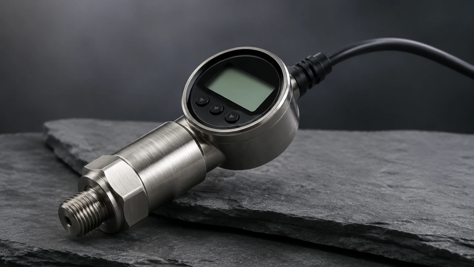
In the realm of industrial process control, the ability to monitor fluid levels and line pressures accurately is a fundamental requirement. While traditional pressure transducers convert mechanical force into an electrical signal for remote monitoring, the integration of a local readout has revolutionized field operations. A pressure transducer with display serves as both a high-precision sensor and a localized indicator, providing real-time data to technicians on the factory floor without the need for secondary handheld devices or control room verification.
For engineers and facility managers, selecting the right instrumentation involves understanding the intersection of sensing physics and human-machine interface (HMI) requirements. This guide explores the technical foundations, selection criteria, and practical applications of pressure transducers equipped with integrated displays, specifically within the context of industrial level measurement.
Measurement Principles: From Pressure to Level
To understand the utility of a pressure transducer with display, one must first grasp the underlying physics of hydrostatic level measurement. In most industrial tank applications, the level of a liquid is determined by the pressure exerted by the liquid column at a specific point, typically the bottom of the vessel.
The Hydrostatic Law
The principle is governed by the formula:
P = ρ × g × h
Where:
* P is the hydrostatic pressure (measured in Pascals or bar).
* ρ (rho) is the density of the liquid (kg/m³).
* g is the acceleration due to gravity (approximately 9.81 m/s²).
* h is the height of the liquid column (meters).
Because gravity and (usually) density are constants for a specific process, the pressure measured by the transducer is directly proportional to the height of the liquid. A pressure transducer with display takes this raw pressure reading, processes it through internal circuitry, and presents the value in user-defined units such as meters (m), centimeters (cm), or bar.
Sensing Technologies
The "sensing" part of the transducer typically relies on one of two primary technologies:
1. Piezoresistive Sensors: These utilize a silicon or metal diaphragm with strain gauges diffused into the surface. When pressure is applied, the diaphragm deforms, changing the electrical resistance. These are highly sensitive and ideal for clean liquids.
2. Ceramic Capacitive Sensors: These use a ceramic diaphragm that acts as one plate of a capacitor. Pressure changes the distance between the ceramic plate and a substrate, altering the capacitance. These are exceptionally rugged and resistant to corrosive chemicals and mechanical abrasion.
The Role of the Integrated Display
The addition of a display to a standard transducer housing provides several critical advantages in a B2B industrial environment. Modern units typically feature LCD (Liquid Crystal Display) or LED (Light Emitting Diode) screens.
Local Visibility and Safety
In large-scale chemical plants or water treatment facilities, the control room may be hundreds of meters away from the actual tank. A pressure transducer with display allows maintenance personnel to perform routine checks or emergency troubleshooting directly at the source. This immediate feedback is vital during manual filling operations or when verifying the status of a pump.
Field Calibration and Configuration
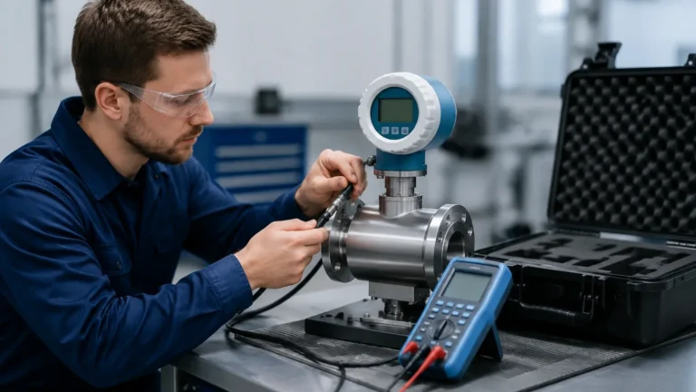
Traditional transducers often require a separate communicator (like a HART handheld) or a laptop to change settings. Units with integrated displays and push-buttons allow for "on-the-spot" configuration. Users can set zero and span points, adjust damping factors, or switch measurement units (e.g., from bar to psi) without opening the housing or interrupting the signal loop.
Diagnostic Feedback
Beyond showing the pressure or level, the display acts as a diagnostic tool. It can show error codes (e.g., sensor failure, over-range, or loop current errors), which significantly reduces the Mean Time to Repair (MTTR) in industrial settings.
Selection Criteria for Industrial Applications
Choosing a pressure transducer with display requires a detailed analysis of the process environment. Engineers should consult the Main Page of a professional manufacturer to review specific model capabilities, but the following factors are universal:
1. Pressure Range and Overpressure Rating
The sensor must be rated for the maximum expected height of the liquid. However, it is equally important to consider the overpressure rating—the maximum pressure the sensor can withstand without permanent damage. For example, a tank that is 10 meters tall exerts approximately 1 bar of pressure at the bottom. A sensor with a 0-2 bar range would be appropriate, provided its overpressure limit accounts for potential surges or accidental overfilling.
2. Media Compatibility
The wetted parts (the parts of the sensor that touch the liquid) must be chemically compatible with the process fluid. Common materials include:
* 316L Stainless Steel: Standard for water, oils, and mild chemicals.
* Ceramic (Al2O3): Excellent for abrasive slurries and aggressive acids.
* PTFE/FEP Coatings: Used for high-purity or extremely corrosive applications.
3. Output Signals
While the display provides local data, the transducer must still communicate with the PLC (Programmable Logic Controller) or SCADA system. Standard outputs include:
* 4-20mA (2-wire): The industry standard for long-distance transmission with high noise immunity.
* 0-10V: Common in HVAC and smaller automation systems.
* RS485/Modbus: For digital networking and multi-parameter data transmission.
4. Environmental Protection
Since these devices are often installed outdoors or in wash-down areas, the ingress protection (IP) rating is paramount. An IP65 rating is usually the minimum for indoor industrial use, while IP67 or IP68 is required for outdoor or submersible applications.
Comparison of Display and Sensor Types
| Feature | LCD Display | LED Display | Piezoresistive Sensor | Ceramic Sensor |
| :— | :— | :— | :— | :— |
| Visibility | Best in direct sunlight | Best in dark/indoor areas | N/A | N/A |
| Power Consumption | Very Low | Higher | N/A | N/A |
| Accuracy | N/A | N/A | High (up to 0.1% FS) | Moderate (0.5% FS) |
| Chemical Resistance | N/A | N/A | Moderate | Excellent |
| Operating Temp | -20°C to +70°C | -40°C to +85°C | -40°C to +125°C | -40°C to +150°C |
Installation Considerations
Proper installation is critical to ensuring the longevity and accuracy of a pressure transducer with display. Unlike remote sensors, the orientation of the display must be considered for operator ergonomics.
* Positioning: The sensor should be installed at the lowest point of the tank measurement range. If the tank has a "dead zone" at the bottom where sediment collects, the sensor should be mounted slightly above the floor or protected by a stilling well.
* Venting: For gauge pressure measurements (relative to atmospheric pressure), the sensor housing or cable must be vented. This allows the sensor to compensate for changes in barometric pressure. Ensure the vent tube is protected from moisture and debris.
* Mounting: Use appropriate thread sealants (like PTFE tape) for NPT or G-type threads. Avoid over-tightening, which can stress the sensor housing and affect the calibration.
* Wiring: Use shielded cables to prevent electromagnetic interference (EMI) from nearby motors or variable frequency drives (VFDs) from affecting the signal or the display stability.
Limitations and Potential Risks
While highly versatile, a pressure transducer with display has specific limitations that engineers must manage:
1. Temperature Sensitivity: Both the sensing element and the electronic display are sensitive to extreme temperatures. High process temperatures (above 100°C) may require the use of a cooling neck or a capillary tube to isolate the electronics from the heat.
2. Display Lag: In some digital displays, there may be a slight lag between the physical pressure change and the visual update. This is usually negligible in level applications but should be noted for high-speed pressure surge monitoring.
3. Sediment and Clogging: In applications involving wastewater or slurries, the pressure port can become clogged. Using a flush-diaphragm design instead of a recessed port can mitigate this risk.
4. Ambient Light: Standard LCDs can be difficult to read in low-light environments without a backlight, while LEDs may wash out in direct, intense sunlight. Selecting the correct display technology for the location is essential.
Frequently Asked Questions (FAQ)
Q: Can a pressure transducer with display be used for vacuum measurement?
A: Yes, many models are designed to measure compound pressure (both vacuum and positive pressure). Ensure the selected range covers the full vacuum (-1 bar) if required.
Q: How often should the display be calibrated?
A: While the display itself is just a readout of the internal digital signal, the underlying sensor should typically be calibrated annually in industrial settings to account for sensor drift. The integrated display makes this process easier by allowing for local zero/span adjustments.
Q: Is a display-equipped transducer suitable for hazardous areas?
A: Yes, but you must specify an intrinsically safe (Ex ia) or explosion-proof (Ex d) version. These versions include specialized housings and energy-limiting circuitry to prevent ignition in flammable atmospheres.
Q: What is the difference between a pressure transmitter and a pressure transducer?
A: In common industrial parlance, the terms are often used interchangeably. Technically, a transducer converts pressure into a low-level voltage signal, while a transmitter converts it into a standardized current signal (like 4-20mA) suitable for long-distance transmission. Most "pressure transducers with display" are technically transmitters.
Conclusion
The integration of a digital display into a pressure transducer represents a significant step forward in industrial usability. By providing immediate, accurate, and actionable data at the point of measurement, these devices enhance safety, simplify maintenance, and improve process transparency. Whether used in water management, chemical processing, or general industrial automation, the pressure transducer with display remains a cornerstone of modern level measurement strategy. For those seeking specific technical specifications or custom OEM solutions, visiting a specialized manufacturer's resource like the Main Page is the recommended next step in the procurement and engineering process.