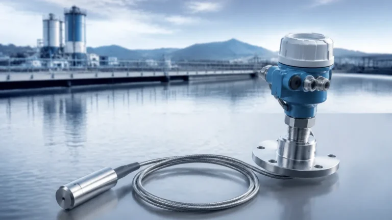
Pressure Decoder
Pressure Decoder
In the field of industrial process control, the term "pressure decoder" refers to the sophisticated electronic signal processing unit integrated within pressure-based level measurement instruments. While the sensor element detects physical force, the pressure decoder is responsible for translating that raw mechanical or electrical change into a meaningful, calibrated value such as liquid level, volume, or mass. Understanding how this decoding process works is essential for engineers tasked with selecting and maintaining instrumentation in water treatment, chemical processing, and oil and gas industries.
Industrial level measurement often relies on hydrostatic pressure, where the weight of a liquid column exerts force on a diaphragm. However, the raw signal generated by a sensor—whether it be a change in capacitance or resistance—is rarely usable in its native state. The pressure decoder acts as the bridge between the physical environment and the digital control system, ensuring that data is accurate, compensated for environmental variables, and formatted for industrial communication protocols.
The Physics of Pressure-to-Level Conversion
To understand the role of a pressure decoder, one must first review the fundamental principle of hydrostatic level measurement. The relationship between the pressure at the bottom of a tank and the height of the liquid is defined by the hydrostatic law:
P = ρ × g × h
Where:
- P is the hydrostatic pressure (measured in Pascals or Bar).
- ρ (rho) is the density of the liquid (kg/m³).
- g is the acceleration due to gravity (approximately 9.81 m/s²).
- h is the height of the liquid column (meters).
The pressure decoder is programmed with these constants. In a standard application, the device measures the pressure (P) and, assuming gravity (g) and density (ρ) are known, calculates the height (h). If the density of the fluid changes due to temperature fluctuations, a sophisticated pressure decoder can utilize an integrated temperature sensor to apply a compensation algorithm, maintaining accuracy even as the physical properties of the media shift.
Signal Processing and Data Interpretation
The internal architecture of a modern pressure decoder involves several critical stages of signal conditioning. When a process engineer reviews options on a Main Page for level instrumentation, they are often looking at the results of this complex internal processing.
1. Analog-to-Digital Conversion (ADC)
Most primary sensing elements produce an analog voltage or current. The pressure decoder first passes this signal through a high-resolution ADC (often 16-bit or 24-bit) to convert the continuous physical signal into a discrete digital value. This allows for noise filtering and mathematical manipulation that would be impossible in the analog domain.
2. Linearization and Characterization
No sensor is perfectly linear across its entire operating range. During manufacturing, the pressure decoder is loaded with a characterization map. This map allows the electronics to correct for known non-linearities in the sensor's response, ensuring that a 50% increase in pressure results in exactly a 50% increase in the reported level.
3. Temperature Compensation
Temperature is the enemy of precision in pressure measurement. Changes in temperature can cause the sensor diaphragm to expand or contract and can alter the viscosity of internal fill fluids. The pressure decoder monitors an internal thermistor and applies real-time offsets to the pressure calculation to negate these thermal effects.
4. Protocol Encoding
Once the level is calculated, the pressure decoder must transmit this information. It "encodes" the data into standard formats such as a 4-20 mA analog loop, or digital protocols like HART, Modbus RS485, or Foundation Fieldbus. This ensures the PLC (Programmable Logic Controller) or SCADA system can interpret the data without error.
Key Selection Criteria for Industrial Applications
Selecting a device with an appropriate pressure decoder requires an analysis of both the process media and the environmental conditions. Not all decoders are created equal; some are optimized for high-speed response, while others prioritize long-term stability in harsh conditions.
Accuracy and Resolution
In high-value chemical storage, a small error in level measurement can equate to thousands of liters of discrepancy. Engineers should look for decoders that offer high reference accuracy (e.g., ±0.075% or ±0.1% of span). The resolution of the internal ADC determines the smallest change in level the device can detect.
Media Compatibility and Diaphragm Seals
The pressure decoder is protected from the process by a diaphragm. For corrosive media like sulfuric acid or brine, the diaphragm must be constructed from resistant materials such as Tantalum, Hastelloy C, or Monel. If the media is prone to clogging or contains solids, a flush-mounted diaphragm is preferred over a threaded process connection to prevent buildup that would interfere with the pressure signal.
Pressure Range and Overpressure Protection
The decoder must be matched to the expected pressure range of the tank. If a sensor with a 1 Bar range is installed in a tank that generates 5 Bar of pressure, the sensor will be damaged. Furthermore, the decoder should have built-in overpressure protection to prevent catastrophic failure during process upsets.
Installation and Configuration Best Practices
The performance of a pressure decoder is heavily dependent on correct installation. Even the most advanced electronics cannot compensate for poor mechanical placement.
Venting for Gauge Pressure
For atmospheric (open) tanks, the pressure decoder must compare the liquid pressure against the local atmospheric pressure. This is typically achieved through a vented cable or a vent plug on the transmitter housing. If this vent becomes blocked by moisture or debris, the decoder will produce an erratic reading as local barometric pressure changes.
Mounting Position and Zero Calibration
Hydrostatic transmitters should be mounted as close to the bottom of the vessel as possible to utilize the full range of the liquid column. Once installed, a "zero trim" or "zero calibration" must be performed. This tells the pressure decoder to ignore the constant weight of the diaphragm and any mounting offsets, setting the baseline for a 0% level reading.
Avoiding Turbulence and Vibration
If the transmitter is installed near an agitator or a high-velocity inlet, the resulting turbulence can cause "noise" in the pressure signal. While a high-quality pressure decoder includes digital damping (averaging the signal over a set number of seconds), it is better practice to install the sensor in a stilling well or a quiet zone of the tank to ensure a stable primary signal.

Limitations and Operational Risks
While pressure-based level measurement is a robust and cost-effective technology, there are specific scenarios where a pressure decoder may struggle to provide accurate data.
* Varying Density: If a tank is used for multiple different chemicals with different densities, the pressure decoder will report different levels for the same physical height unless the density constant is updated in the software.
* Pressurized Vessels: In a closed tank, the pressure at the bottom is the sum of the liquid height AND the gas pressure above the liquid. In these cases, a differential pressure (DP) transmitter is required. The pressure decoder in a DP transmitter subtracts the top gas pressure from the total bottom pressure to isolate the liquid level.
* Sediment Buildup: In wastewater or mining slurries, sediment can settle on the diaphragm. This adds "false weight" to the sensor, leading the pressure decoder to report a higher level than actually exists. Regular cleaning or the use of non-clogging sensor designs is required.
Practical Selection Table
| Application Type | Recommended Sensor Material | Decoder Communication | Key Consideration |
| :— | :— | :— | :— |
| Potable Water | Stainless Steel 316L | 4-20mA / HART | Long-term stability, NSF certification |
| Corrosive Chemicals | Hastelloy / PTFE Coated | Modbus RS485 | Chemical resistance of the diaphragm |
| Wastewater Slurry | Ceramic Diaphragm | 4-20mA | Abrasion resistance and non-clogging design |
| Fuel/Oil Storage | Stainless Steel | Explosion Proof (Ex d/ia) | Intrinsically safe electronics |
| Deep Wells | Titanium (optional) | Submersible Cable | Hydrostatic pressure range vs. depth |
Frequently Asked Questions
Q: Can a pressure decoder measure the level of solids?
No. Pressure-based measurement relies on the fluid nature of liquids to exert equal pressure in all directions. Solids like grain or sand do not exert hydrostatic pressure in the same way, and measurement would be highly inaccurate. For solids, radar or ultrasonic technologies are preferred.
Q: How often should the pressure decoder be calibrated?
In most industrial applications, an annual calibration check is recommended. However, in critical safety loops or highly corrosive environments, semi-annual checks may be necessary to ensure the electronics haven't drifted.
Q: What is the difference between a pressure transmitter and a pressure decoder?
Technically, the pressure decoder is a component *inside* the pressure transmitter. The transmitter is the whole device, while the decoder is the specific logic and circuitry that interprets the sensor's signal.
Q: Does the length of the cable affect the decoding?
If using a digital output (like Modbus) or a 4-20mA current loop, cable length has minimal impact on accuracy over standard industrial distances. However, for raw millivolt signals, cable length and shielding are critical to prevent signal degradation before it reaches the decoder.
For engineers and procurement specialists looking for reliable level measurement hardware, it is vital to source equipment from manufacturers who prioritize signal integrity. Detailed technical specifications and product ranges can be found on the Main Page of industry-leading suppliers, providing the necessary data to match the right pressure decoder to the specific demands of the process environment.