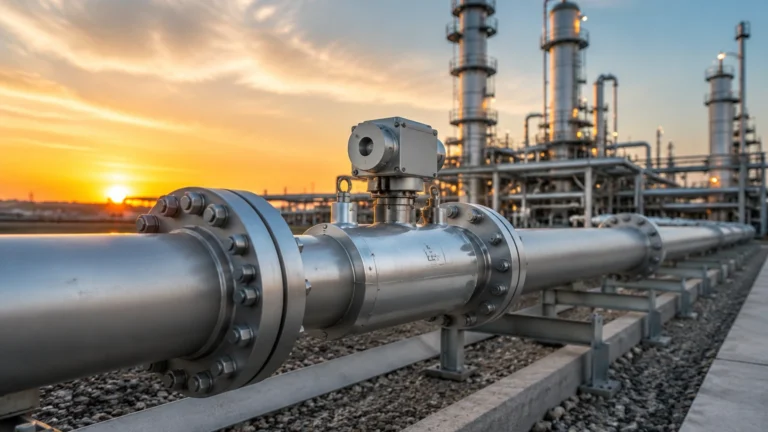
Process Flow Metering
Process Flow Metering
Process flow metering is a fundamental requirement in modern industrial automation, serving as the primary method for monitoring and controlling the movement of fluids through a system. Whether in water treatment, chemical processing, or oil and gas extraction, the ability to accurately quantify flow rates is essential for process efficiency, safety, and billing accuracy. While many engineers immediately think of inline flow meters, such as electromagnetic or turbine meters, a significant portion of industrial flow measurement—particularly in open channels and large tanks—relies heavily on advanced level measurement technologies.
In these applications, the relationship between liquid level and flow rate is governed by established hydraulic principles. By measuring the head or level of a fluid as it passes through a known geometry, such as a weir or flume, operators can calculate the volumetric flow rate with high precision. This guide explores the principles, technologies, and selection criteria for process flow metering through the lens of level-based measurement solutions.
Understanding the Principles of Process Flow Metering
Before selecting an instrument, it is critical to understand the physical principles that allow a level sensor to function as a flow meter. This is most commonly seen in open channel flow and tank discharge monitoring.
Open Channel Flow (Weirs and Flumes)
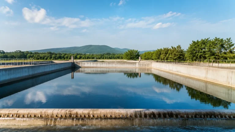
In open channel systems, flow is not contained within a pressurized pipe. Instead, the fluid flows through a primary device—a weir (a dam-like structure) or a flume (a constricted channel). These devices are designed so that the flow rate is a direct function of the liquid level (head) measured at a specific point upstream.
For example, in a V-notch weir, the flow rate ($Q$) is proportional to the level ($h$) raised to the power of 2.5 ($Q = C × h^{2.5}$), where $C$ is a discharge coefficient based on the notch angle. Because the geometry is fixed, the accuracy of the process flow metering depends entirely on the accuracy of the level measurement.
Hydrostatic Head and Discharge
In closed tanks or vessels, flow can be inferred by the rate of change in level over time or by the hydrostatic pressure at the outlet. Hydrostatic level transmitters measure the pressure exerted by a liquid column, which is directly proportional to the height of the liquid ($P = ρgh$). When the outlet characteristics are known, this pressure data provides the necessary input for calculating discharge flow rates.
Key Technologies in Process Flow and Level Measurement
Welk provides a range of industrial instruments designed to meet the rigors of process flow metering. Each technology offers distinct advantages depending on the media and environmental conditions.
Radar Level Meters
Radar technology has become the gold standard for non-contact level measurement in flow applications. Operating at high frequencies (such as 26GHz or 80GHz), these meters emit microwave pulses that reflect off the liquid surface.
* Advantages: Radar is unaffected by temperature fluctuations, vacuum, high pressure, or the presence of dust and steam. In open channel flow, radar provides a stable reading even if the liquid surface is slightly turbulent.
* Application: Ideal for chemical processing where the media may be corrosive or volatile, necessitating a non-contact approach.
Ultrasonic Level Sensors
Ultrasonic sensors use sound waves to determine the distance to the liquid surface. They are widely used in water and wastewater treatment for open channel flow monitoring.
* Advantages: Highly cost-effective and easy to install. Modern ultrasonic sensors include temperature compensation to account for changes in the speed of sound through air.
* Limitations: Ultrasonic waves can be absorbed by heavy foam or scattered by heavy steam, which may lead to signal loss in extreme process environments.
Hydrostatic Level Transmitters
For applications where the sensor must be submerged or where the tank is vented to the atmosphere, hydrostatic transmitters are a reliable choice. These devices use a diaphragm to sense the pressure of the liquid column.
* Advantages: Excellent for deep wells or tanks where top-down mounting of radar or ultrasonic sensors is impractical. They provide a direct pressure reading that is easily converted to level and flow.
Evaluation Criteria for Meter Selection
Selecting the right instrument for process flow metering requires a thorough analysis of the application environment. Engineers should evaluate the following criteria:
1. Media Characteristics: Is the fluid clean water, slurry, or a corrosive chemical? Non-contact sensors like radar are preferred for aggressive media to extend the lifespan of the instrument.
2. Process Conditions: Consider the ambient and process temperature. Ultrasonic sensors may struggle in high-heat environments, whereas radar remains stable up to 250°C or higher.
3. Accuracy Requirements: Open channel flow calculations are sensitive to level errors. A small error in head measurement can lead to a large error in calculated flow. High-precision radar (with accuracy up to ±2mm) is often required for billing-grade metering.
4. Installation Space: Does the site have enough headroom for a radar sensor, or is a submerged hydrostatic probe more practical?
Practical Selection Table
The following table provides a comparison of common technologies used in level-based process flow metering applications.
| Technology | Typical Accuracy | Measurement Range | Media Compatibility | Best Use Case |
| :— | :— | :— | :— | :— |
| Radar (80GHz) | ±2 mm | Up to 30m+ | All liquids/solids | High-precision chemical & oil flow |
| Ultrasonic | ±0.25% of range | 0.3m to 15m | Water, wastewater | Municipal water treatment channels |
| Hydrostatic | ±0.5% FS | 1m to 200m | Clean liquids | Deep well and vented tank discharge |
| Magnetic Gauge | ±5 mm | 0.3m to 6m | Clean/Dirty liquids | Visual flow/level confirmation |
For a comprehensive look at available hardware and technical specifications, engineers should visit the Main Page to review product options and application support.
Installation Considerations and Best Practices
Even the most accurate sensor will fail to provide reliable process flow metering data if installed incorrectly. Follow these engineering guidelines to ensure system integrity:
1. Positioning Relative to Primary Devices
In open channel flow, the level sensor must be installed at a specific distance upstream from the weir or flume. This distance is usually 3 to 4 times the maximum head ($H_{max}$) to avoid the "draw-down" effect where the water level begins to drop as it approaches the crest of the weir.
2. Avoiding Turbulence and Foam
Flow is rarely perfectly smooth. Turbulence can cause the liquid surface to ripple, leading to "noisy" data. In such cases, a stilling well (a vertical pipe submerged in the liquid) can be used to provide a calm surface for the sensor to measure. If foam is present, radar is generally superior to ultrasonic, as microwaves can penetrate foam more effectively than sound waves.
3. Straight Run Requirements
For any flow-related measurement, the approach channel should be straight and free of obstructions for a distance of at least 10 times the channel width. This ensures a laminar flow profile, which is a prerequisite for accurate level-to-flow conversion formulas.
4. Dead Zone Management
Ultrasonic and radar sensors have a "dead zone" (or blocking distance) directly beneath the sensor face where measurements cannot be taken. Ensure the sensor is mounted high enough so that even at the maximum possible flow/level, the liquid does not enter this zone.
Limitations and Common Risks
While level-based process flow metering is highly effective, it is not without risks. Understanding these limitations is key to maintaining a robust system.
* Sedimentation: In weir and flume applications, solids can settle at the bottom of the primary device over time. This changes the geometry of the channel and leads to over-estimation of flow. Regular cleaning is mandatory.
* Environmental Interference: For ultrasonic sensors, heavy wind or significant temperature gradients between the liquid and the sensor can refract the sound waves. Using a protective sunshade or choosing radar can mitigate these effects.
* Build-up on Sensors: In applications involving sticky or crystallizing fluids, material can build up on the sensor face. While many Welk radar meters feature non-stick PTFE faces, periodic inspection is recommended to ensure signal strength remains optimal.
Frequently Asked Questions (FAQs)
Q: Can I use a level sensor to measure the flow of solids?
A: Indirectly, yes. In silo discharge applications, the rate of level decrease (drawdown) can be used to estimate the mass flow of solids, provided the bulk density of the material is consistent.
Q: How often should a process flow metering system be calibrated?
A: This depends on the industry. For municipal water, annual calibration is common. For high-value chemical processes, semi-annual verification of the level sensor against a manual reference (like a dip tape) is recommended.
Q: What is the benefit of 80GHz radar over 26GHz for flow?
A: 80GHz radar has a much narrower beam angle. This allows it to be installed in narrow channels or near walls without receiving false echoes from the sides of the structure, which is a common issue in process flow metering.
Q: Do I need a separate flow computer?
A: Many modern transmitters from Welk include built-in flow linearization tables for standard weirs and flumes. This allows the sensor to output the flow rate directly via 4-20mA or RS485 Modbus, eliminating the need for an external flow computer.
Conclusion
Effective process flow metering is a combination of sound hydraulic engineering and the application of precise measurement technology. By understanding the principles of open channel flow and hydrostatic pressure, and by selecting the appropriate radar, ultrasonic, or hydrostatic instruments, industrial operators can achieve reliable data for their most critical processes.
When designing a system, always account for the specific characteristics of the media and the physical constraints of the installation site. For those seeking to implement or upgrade their measurement capabilities, consulting a professional manufacturer like Welk ensures access to the latest technological advancements and customized support. To explore the full range of instruments suitable for these applications, please refer to the Main Page for detailed technical documentation and product selection guides.