Proline Prowirl
Proline Prowirl
In the landscape of industrial process automation, the accurate measurement of fluids—whether liquid, gas, or steam—is fundamental to operational efficiency and safety. The Proline Prowirl series represents a significant segment of the vortex flowmeter market, designed to provide robust and reliable data in challenging environments. While often discussed in isolation, these instruments frequently operate in tandem with other process sensors, including the level measurement technologies found on the Main Page, to provide a holistic view of plant performance.
This guide examines the technical foundations of the Proline Prowirl, its various configurations, and the critical engineering considerations required for successful deployment in industrial piping systems.
Measurement Principle: The Von Kármán Vortex Street
Before selecting a specific model within the Proline Prowirl family, it is essential to understand the physical principle that governs its operation. Vortex flowmeters operate based on the Von Kármán vortex street principle.
When a fluid flows past a non-streamlined object (known as a bluff body) placed in the center of a pipe, it cannot follow the contours of the object on both sides simultaneously. This results in the fluid layers separating and curling into vortices, or small eddies, which are shed alternately from each side of the bluff body.
The Relationship Between Frequency and Velocity
The frequency at which these vortices are shed is directly proportional to the velocity of the fluid flow. This relationship is defined by the Strouhal number (Sr), a dimensionless parameter that remains constant over a wide range of Reynolds numbers. The formula is generally expressed as:
f = (Sr × v) / d
Where:
* f is the vortex shedding frequency.
* Sr is the Strouhal number.
* v is the flow velocity.
* d is the width of the bluff body.
Because the width of the bluff body and the internal pipe diameter are known constants, the meter can accurately calculate the volume flow by measuring the frequency of the pressure fluctuations caused by the vortices. These fluctuations are typically detected by a capacitive DSC (Differential Switched Capacitor) sensor, which is designed to be resistant to pipe vibrations and thermal shocks.
Technical Overview of the Proline Prowirl Series
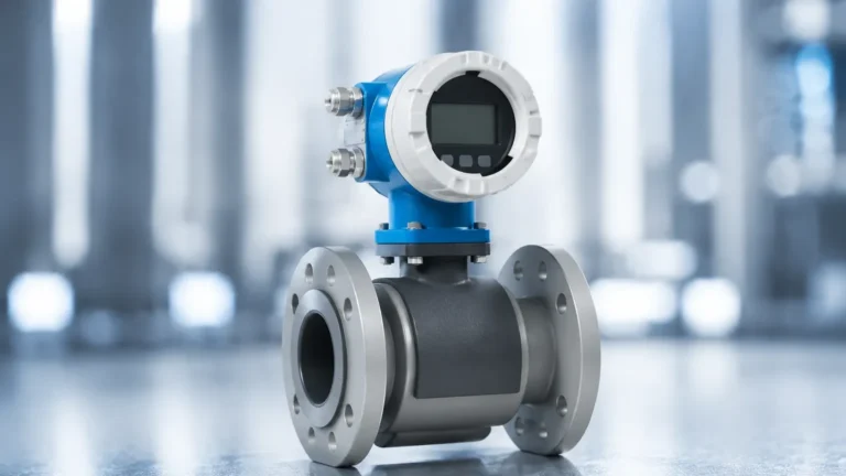
The Proline Prowirl range is categorized into several distinct models, each optimized for specific process conditions. Understanding these variations is critical for matching the instrument to the application requirements, particularly when dealing with steam or high-pressure gases.
Prowirl F 200
The "F" variant is the universal flowmeter for the series. It is designed for a broad spectrum of applications in liquids, gases, and steam. Its primary advantage is its versatility across different pipe sizes and pressure ratings. It is often used in utility applications where standard flanged connections are preferred.
Prowirl R 200
The "R" variant (Reduced Bore) features an integrated diameter reduction. In many steam applications, the pipe size is often oversized for the actual flow rate to minimize pressure drop. However, vortex meters require a minimum flow velocity to shed vortices reliably. The Prowirl R allows for accurate measurement in low-flow conditions without the need for external pipe reducers, saving on installation costs and space.
Prowirl O 200
The "O" variant is engineered for high-pressure applications. It is characterized by its specialized flange designs and reinforced sensor housing, making it suitable for demanding environments in the oil and gas or chemical sectors where process pressures exceed standard ratings.
Selection Table: Comparative Specifications
| Feature | Prowirl F | Prowirl R | Prowirl O |
| :— | :— | :— | :— |
| Primary Application | Universal (Liquid/Gas/Steam) | Low-flow / Steam | High-Pressure Applications |
| Nominal Diameter | DN 15 to 300 (1/2" to 12") | DN 25 to 200 (1/2" to 8") | DN 15 to 150 (1/2" to 6") |
| Process Temperature | -200 to +400 °C | -200 to +400 °C | -200 to +400 °C |
| Max Pressure | Up to PN 40 / Class 300 | Up to PN 40 / Class 300 | Up to PN 250 / Class 1500 |
| Accuracy (Liquid) | ±0.75% | ±0.75% | ±0.75% |
| Accuracy (Steam/Gas) | ±1.0% | ±1.0% | ±1.0% |
Integration with Level Measurement Systems
In industrial engineering, flow measurement rarely exists in a vacuum. The data provided by a Proline Prowirl is frequently integrated with level measurement data to manage complex systems like boilers, storage tanks, and distillation columns.
For instance, in a steam boiler system, the Prowirl measures the steam output (mass flow), while a hydrostatic or guided wave radar level transmitter (technologies extensively detailed on the Main Page) monitors the water level within the drum. By comparing the mass of water entering the boiler with the mass of steam leaving it, engineers can implement "three-element control" to maintain stable water levels during rapid load changes.
This synergy between flow and level measurement ensures that the mass balance of the system is maintained, preventing dangerous dry-run conditions in boilers or overfill scenarios in separator vessels.

Installation Considerations and Best Practices
The accuracy of a vortex flowmeter is highly dependent on the flow profile of the fluid as it enters the meter. Turbulent or swirling flow can lead to significant measurement errors.
Straight Pipe Runs
To ensure a fully developed flow profile, the Proline Prowirl must be installed with specific lengths of straight pipe upstream and downstream of the unit.
* Upstream: Typically requires 20 times the nominal diameter (20xDN) if following a single 90° bend. If following a pump or a pressure-reducing valve, this may increase to 40xDN.
* Downstream: Typically requires 5 times the nominal diameter (5xDN) to prevent back-pressure disturbances from affecting the sensor.
Orientation and Mounting
* Horizontal Pipes: For liquid applications, the meter should be installed in a position where the pipe is always full. For steam or gas, the sensor should be mounted to the side or top to prevent condensate or debris from collecting on the bluff body.
* Vertical Pipes: Flow should ideally be in an upward direction for liquids to ensure the pipe remains full. For steam and gas, downward flow is permissible provided the system is properly drained.
Vibration and Support
While the DSC sensors in the Prowirl are designed to filter out typical plant vibrations, excessive mechanical stress can interfere with the vortex signal. It is recommended to support the piping on both sides of the meter, especially in high-vibration environments or when using larger meter sizes.
Limitations and Application Risks
Despite its robustness, the Proline Prowirl is not suitable for every application. Engineers must be aware of the following limitations:
1. Minimum Reynolds Number: Vortex meters require a minimum fluid velocity to function. If the flow rate falls below the "low-flow cut-off," the meter will read zero, even if some fluid is moving. This is particularly relevant in batch processes or systems with high turndown requirements.
2. Multiphase Flow: Vortex meters are designed for single-phase fluids. The presence of significant gas bubbles in a liquid, or liquid droplets in a gas (wet steam), will degrade accuracy and can potentially damage the sensor over time due to cavitation or water hammer.
3. Abrasive Fluids: Because the bluff body is directly in the flow path, fluids containing high concentrations of abrasive solids will cause wear on the leading edge of the bluff body. This changes the Strouhal number and leads to a permanent shift in calibration.
Frequently Asked Questions (FAQs)
How does the Proline Prowirl handle temperature and pressure compensation?
Modern Prowirl units are often "multivariable," meaning they include integrated temperature sensors and can accept an external pressure signal. This allows the meter to calculate mass flow and energy flow (especially for steam) in real-time, rather than just reporting volume flow.
Can the sensor be replaced without breaking the process line?
In many configurations, the DSC sensor is located behind a secondary containment and can be replaced without interrupting the process, provided the system is not at extreme pressure. This significantly reduces downtime during maintenance cycles.
What is the significance of "Heartbeat Technology" in these meters?
Heartbeat Technology provides continuous self-diagnostics and verification. It allows operators to generate a calibration verification report without removing the meter from the pipe, which is essential for compliance in regulated industries like chemicals and pharmaceuticals.
How does a vortex meter compare to an ultrasonic meter for steam?
Vortex meters like the Prowirl are generally more cost-effective and robust for high-temperature steam. Ultrasonic meters are often preferred for very large pipe diameters where the pressure drop of a bluff body would be unacceptable, or for ultra-pure water where no obstructions are allowed in the pipe.
Why is the Prowirl R used instead of a standard meter with pipe reducers?
Using the Prowirl R eliminates the need for separate concentric reducers and expanders. This reduces the number of potential leak points (flanges), shortens the overall installation length, and ensures that the flow profile is optimized specifically for the meter's internal geometry.
In conclusion, the Proline Prowirl is a versatile tool for industrial fluid measurement. By understanding its physical principles and adhering to strict installation guidelines, engineers can ensure long-term accuracy. When combined with the level measurement solutions discussed on the Main Page, these instruments form the backbone of modern process control and energy management systems.