Pulp and Paper Automation
Pulp and Paper Automation
In the modern industrial landscape, pulp and paper automation represents one of the most complex challenges for process control engineering. The transition from raw timber or recycled fiber to finished paper products involves a series of harsh chemical reactions, high-temperature mechanical processing, and precise fluid management. At the heart of this automation is the need for reliable level measurement. Without accurate data on the volume of wood chips, the concentration of black liquor, or the level of pulp stock in a chest, a mill cannot maintain the consistency required for high-speed paper machines.
Level measurement instruments in this sector must withstand extreme conditions, including corrosive chemicals, high steam concentrations, and heavy mechanical agitation. This guide examines the fundamental principles of level measurement technologies used in pulp and paper automation, providing a framework for selection, installation, and maintenance.
Core Principles of Level Measurement in Paper Mills
Before selecting a device, it is essential to understand the physical principles that govern level measurement in the unique environments of a paper mill.
Radar Level Measurement (Non-Contact and Guided)
Radar technology operates on the principle of Time-of-Flight (ToF). A sensor emits a microwave signal that travels to the surface of the material and reflects back.
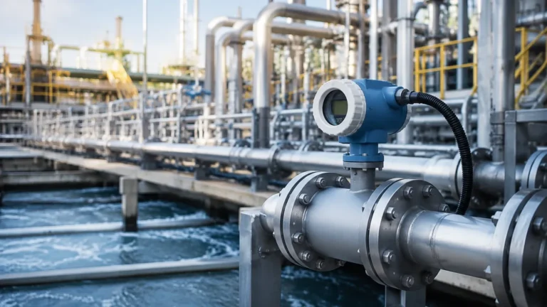
* Non-Contact Radar: These sensors emit electromagnetic pulses (often at 26GHz or 80GHz frequencies). The 80GHz radar is particularly effective in pulp and paper automation because its narrow beam angle can avoid internal tank obstructions like agitators or heating coils. It is unaffected by vacuum, pressure, or temperature shifts.
* Guided Wave Radar (GWR): In GWR, the microwave signal travels along a physical probe (rod or cable). This is ideal for low-dielectric liquids or applications where heavy foam is present, as the probe guides the signal directly to the surface, reducing signal loss.
Ultrasonic Level Sensors
Ultrasonic sensors use sound waves to measure distance. The sensor emits a high-frequency pulse that reflects off the material surface. Because the speed of sound is affected by air temperature and vapor density, these sensors are best suited for ambient-temperature water treatment tanks or chemical storage where steam and heavy vapors are not present.
Hydrostatic Pressure Transmitters
Hydrostatic measurement relies on the principle that the pressure at the bottom of a vessel is proportional to the height of the liquid column and its density ($P = \rho \cdot g \cdot h$). In paper mills, flush-diaphragm transmitters are used for thick pulp stock to prevent the clogging of the sensing element. These are highly reliable but require consistent fluid density to remain accurate.
Magnetic Level Gauges
Magnetic level gauges utilize a float containing a magnet that moves with the liquid level inside a bypass chamber. This motion flips colored flags on an external scale and can be paired with a reed chain transmitter for remote monitoring. They provide both a local visual reference and an electronic signal, making them excellent for high-pressure boiler feedwater applications.
Strategic Implementation of Pulp and Paper Automation
Automation in a mill is not just about replacing manual labor; it is about achieving process stability. In the pulp and paper industry, variability is the enemy of quality. Fluctuations in the level of a headbox, for instance, lead to variations in paper weight and thickness.
Integrated pulp and paper automation systems rely on level data to manage the "Mass Balance" of the mill. This involves tracking the flow of water, chemicals, and fiber through various stages:
1. Chemical Recovery: Level sensors monitor black, green, and white liquor tanks. Accurate measurement ensures that the recovery boiler operates safely and that chemicals are recycled efficiently, reducing environmental impact.
2. Stock Preparation: In the refiners and chests, maintaining a constant level is critical for ensuring uniform fiber consistency. Hydrostatic and radar sensors are often used in tandem here to provide redundancy.
3. Wastewater Treatment: Large-scale clarifiers and basins require robust ultrasonic or non-contact radar sensors to manage the high volumes of water used in the pulping process.
By centralizing this data, mill operators can utilize predictive analytics to identify bottlenecks before they cause downtime. For more detailed technical specifications on these instruments, you can Review product options and application support to see how specific hardware aligns with these automation goals.
Selection Guide: Matching Technology to Process Media
Choosing the right instrument requires an analysis of the media's physical properties. The following table provides a general guideline for technology selection in common pulp and paper applications.
| Application | Media Type | Recommended Technology | Why? |
| :— | :— | :— | :— |
| Wood Chip Silo | Bulk Solid | 80GHz Non-Contact Radar | Penetrates dust; narrow beam avoids wall interference. |
| Digester | Pulp + Chemicals | Guided Wave Radar | Handles high pressure/temperature and steam. |
| Black Liquor Tank | Corrosive Liquid | Non-Contact Radar (PTFE Coated) | Resists corrosion and buildup; no contact with media. |
| Pulp Stock Chest | Thick Slurry | Hydrostatic (Flush Diaphragm) | Prevents clogging; handles high-viscosity fibers. |
| Acid/Alkali Storage | Corrosive Chemical | Ultrasonic or Radar | Non-contact prevents sensor degradation. |
| Boiler Drum | High-Temp Water | Magnetic Level Gauge | Reliable visual and electronic tracking at high pressure. |
| Starch/Additive Tanks | Viscous Liquid | Guided Wave Radar | Accurate even with low dielectric constants. |
Critical Installation and Engineering Considerations
Even the most advanced sensor will fail if the installation does not account for the physical dynamics of the tank. For successful pulp and paper automation, engineers should follow these best practices:
Nozzle Design and Placement
For radar and ultrasonic sensors, the nozzle should be as short as possible. If a nozzle is too long or narrow, it can create "ringing" or false echoes. In pulp stock applications, sensors should be mounted away from the inflow pipe to avoid turbulence and false readings caused by falling material.
Dealing with Agitators
Most tanks in a paper mill use heavy-duty agitators to keep fibers in suspension. When using non-contact radar, the sensor must be mapped to ignore the agitator blades. Using an 80GHz radar with a beam angle as narrow as 3° significantly reduces the likelihood of the signal hitting the blades.
Stilling Wells and Bypass Chambers
In applications with extreme surface turbulence or heavy foam, a stilling well (a pipe inside the tank) or an external bypass chamber can provide a calm surface for the sensor to measure. This is common in chemical recovery and power boiler applications.
Temperature and Pressure Limits
Standard sensors are often rated for temperatures up to 80°C. However, digesters and steam-stripping columns can exceed 150°C. In these cases, sensors must be equipped with cooling fins or high-temperature ceramic seals to protect the electronics.
Addressing Operational Challenges and Limitations
While automation technology has advanced, certain environmental factors in a paper mill still pose significant challenges.
1. Steam and Vapor: In the pulping process, steam can attenuate ultrasonic signals, causing the sensor to "lose" the level. Radar is generally immune to steam, but extremely dense vapors can slightly shift the signal's travel time, requiring a vapor compensation factor in the software.
2. Buildup and Scaling: Black liquor and pulp stock are prone to leaving deposits on sensor faces. PTFE (Teflon) coatings or parabolic antennas are used to minimize adhesion. In extreme cases, air purging systems are installed to blow debris off the sensor face periodically.
3. Foam: Heavy, dense foam can absorb radar signals or reflect them prematurely. Guided wave radar is often the best solution here, as the signal concentrates along the probe and can often penetrate the foam to find the true liquid level.
4. Density Fluctuations: Hydrostatic sensors assume a constant density. If the consistency of the pulp stock changes from 3% to 5%, the level reading will become inaccurate. In these scenarios, radar is preferred as it is density-independent.
Frequently Asked Questions in Mill Instrumentation
Q: How often should level sensors be calibrated in a pulp mill?
A: For critical process loops (like the headbox or digester), sensors should be verified every 6 to 12 months. However, non-contact radar sensors generally require less frequent calibration than hydrostatic sensors because they have no moving parts and do not drift due to density changes.
Q: Can one sensor type be used for the entire mill?
A: While radar is the most versatile, it is not always the most cost-effective. A balanced approach using ultrasonic for water treatment, hydrostatic for stock chests, and radar for chemical tanks is usually the most efficient strategy for pulp and paper automation.
Q: What is the impact of "blanking distance"?
A: The blanking distance (or dead zone) is the area directly beneath the sensor where it cannot measure. If a tank is overfilled into this zone, the sensor may report an incorrect level or an error. It is vital to select a sensor with a blanking distance smaller than the distance between the mounting flange and the maximum possible fill level.
Q: How do I handle measurement in a tank with a spherical bottom?
A: Most modern transmitters allow for "tank linearization." You input the dimensions of the tank (spherical, conical, or horizontal cylindrical) into the sensor's software, and it automatically converts the distance measurement into a volume (liters or cubic meters).
Conclusion
Achieving excellence in pulp and paper automation requires a deep understanding of both the process chemistry and the physics of measurement. By selecting the appropriate technology—whether it be the precision of 80GHz radar or the rugged reliability of hydrostatic transmitters—mills can reduce waste, improve product quality, and ensure a safer working environment. For engineers looking to upgrade their current systems or design new installations, visiting the Main Page provides access to a comprehensive range of industrial level measurement solutions tailored for these demanding applications.