Pumping Co2 for Storage and Transport
Pumping Co2 for Storage and Transport
Carbon Capture, Utilization, and Storage (CCUS) has emerged as a critical pillar in global efforts to mitigate industrial greenhouse gas emissions. Central to the success of these initiatives is the infrastructure required for pumping CO2 for storage and transport. Moving carbon dioxide from the point of capture—such as power plants or industrial facilities—to a permanent sequestration site or a utilization hub requires sophisticated pumping systems and precise instrumentation.
Because carbon dioxide exhibits unique thermodynamic properties, the engineering requirements for its transport differ significantly from those of water or traditional hydrocarbons. This guide explores the technical foundations of CO2 pumping, the measurement principles essential for process control, and the selection criteria for maintaining system integrity in high-pressure environments.
The Thermodynamics of CO2 Transport
To understand the requirements for pumping CO2 for storage and transport, one must first examine the phase behavior of carbon dioxide. CO2 is typically transported in a "dense phase," which includes both the liquid state and the supercritical state.
Liquid vs. Supercritical Phase
At ambient temperatures and high pressures (typically above 60 bar), CO2 exists as a liquid. If the temperature exceeds the critical point of 31.1°C (87.9°F) and the pressure exceeds 73.8 bar (1,070 psi), it becomes a supercritical fluid. In this state, it possesses the density of a liquid but the viscosity of a gas.
Transporting CO2 in the dense phase is preferred because it maximizes the mass flow rate while minimizing the pipeline diameter and energy requirements. Pumping a dense fluid is significantly more efficient than compressing a gas. However, maintaining these phases requires rigorous pressure and level control within storage vessels and pump stations to prevent phase transitions that could lead to cavitation or equipment damage.
Measurement Principles for CO2 Systems
In any CO2 transport or storage system, accurate level and pressure measurement are vital for safety and efficiency. Before selecting hardware, engineers must understand the physical principles that govern how these instruments interact with carbon dioxide.
Guided Wave Radar (GWR)
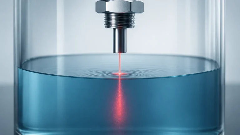
Guided Wave Radar is a common choice for CO2 level measurement. It operates on the principle of Time Domain Reflectometry (TDR). A low-energy electromagnetic pulse is sent down a probe (the waveguide). When the pulse hits the surface of the liquid CO2, a portion of the energy is reflected back to the transmitter.
One challenge with CO2 is its low dielectric constant (εr ≈ 1.6 in liquid state). Because the reflection strength depends on the difference in dielectric constants between the upper vapor phase and the lower liquid phase, high-sensitivity electronics are required to detect the signal. In high-pressure storage, the vapor phase density increases, which can slow down the electromagnetic pulse, necessitating a gas phase compensation feature to maintain accuracy.
Hydrostatic Level Measurement
Hydrostatic transmitters measure the pressure exerted by the liquid column. The principle is based on the formula: $P = \rho gh$, where $P$ is pressure, $\rho$ is the density of the fluid, $g$ is gravity, and $h$ is the height of the liquid.
In CO2 applications, this method is highly reliable but requires precise temperature compensation. Since the density of CO2 is highly sensitive to temperature fluctuations, a change in temperature will change the pressure reading even if the actual level remains constant. Differential pressure (DP) transmitters are often used in pressurized tanks to subtract the top-side vapor pressure from the total bottom pressure.
Ultrasonic Level Sensors
Ultrasonic sensors use sound waves to measure the distance to the fluid surface. While cost-effective for water treatment, they are generally not recommended for high-pressure CO2 storage. The high-density gas or supercritical fluid above the liquid can significantly alter the speed of sound, and the acoustic impedance mismatch at high pressures often leads to signal loss.
Pumping Technologies for Dense Phase CO2
The selection of a pump for CO2 transport depends on the required flow rate and the necessary pressure boost.
1. Centrifugal Pumps: Multi-stage centrifugal pumps are the industry standard for high-volume CO2 transport. They are designed to handle the high suction pressures inherent in CO2 systems. Special attention is paid to the mechanical seals, as CO2 can act as a solvent and degrade standard elastomers.
2. Reciprocating (Plunger) Pumps: These are used for lower flow rates but very high-pressure applications, such as EOR (Enhanced Oil Recovery) injection wells. They offer high volumetric efficiency but require pulsation dampeners to protect downstream instrumentation.
Selection Table for Level Instrumentation
| Technology | Suitability for CO2 | Primary Advantage | Limitation |
| :— | :— | :— | :— |
| Guided Wave Radar | Excellent | Precise, independent of density changes | Requires gas phase compensation at high pressure |
| Hydrostatic (DP) | Good | Proven technology, easy to maintain | Highly dependent on accurate density data |
| Non-Contact Radar | Good | No moving parts, no contact with fluid | Sensitive to surface foam or turbulence |
| Magnetic Level Gauge | Excellent | Visual indication without power | Limited to specific pressure ratings of the chamber |
| Ultrasonic | Poor | Low cost | Inaccurate in high-pressure gas environments |
Installation Considerations for CO2 Infrastructure
When installing instrumentation for pumping CO2 for storage and transport, several engineering factors must be addressed to ensure long-term reliability.
Material Compatibility
Carbon dioxide in the presence of moisture forms carbonic acid, which is highly corrosive to carbon steel. Therefore, all wetted parts of pumps and level meters should be constructed from 316L stainless steel or higher-grade alloys. Furthermore, elastomers must be selected to resist "Explosive Decompression" (ED). If CO2 permeates an O-ring at high pressure and the system is suddenly depressurized, the gas trapped inside the elastomer expands rapidly, causing the seal to rupture.
Stilling Wells and Bypass Chambers
For radar-based level measurement, using a stilling well or an external bypass chamber is recommended. This protects the probe from the turbulence created by high-capacity pumps and ensures a stable surface for measurement. In CO2 applications, these chambers must be rated for the full design pressure of the system, often exceeding 100 bar (1,450 psi).
Venting and Sealing
CO2 is an asphyxiant and is heavier than air. Pump stations and instrument clusters must be designed with proper venting. Leak detection is critical, especially around the seals of rotating equipment. For a comprehensive look at available measurement technologies for these applications, engineers can visit the Main Page of specialized instrument manufacturers.
Limitations and Risks
Despite the advanced technology available, pumping CO2 for storage and transport involves inherent risks:
* Cavitation: If the pressure at the pump inlet drops below the vapor pressure of CO2, the liquid will flash into gas, creating bubbles that collapse violently and erode the pump impellers. Maintaining a high Net Positive Suction Head (NPSH) is mandatory.
* Dry Running: CO2 has poor lubricating properties compared to oils. Pumps must be designed with specialized bearings or be kept fully primed to avoid catastrophic failure.
* Hydrate Formation: If water is present in the CO2 stream, it can form solid hydrates at specific temperature and pressure combinations, which can plug pipes and damage pumps.
Frequently Asked Questions (FAQs)
Q: Why is CO2 pumped as a liquid rather than a gas?
A: Pumping liquid CO2 is much more energy-efficient than compressing gas. Liquid CO2 is much denser, meaning a smaller pump can move a significantly larger mass of carbon compared to a compressor handling the same volume of gas.
Q: What is the impact of impurities on CO2 pumping?
A: Impurities like nitrogen, methane, or hydrogen sulfide can change the critical point and the vapor pressure of the CO2 stream. This requires the pumping system and level instruments to be calibrated for the specific gas mixture rather than pure CO2.
Q: Can hydrostatic level sensors be used in supercritical CO2?
A: Yes, but it is challenging. In the supercritical phase, there is no distinct liquid/gas interface. The sensor would effectively be measuring the mass or density gradient within the vessel rather than a "level."
Q: How do you prevent seal failure in CO2 pumps?
A: Using double mechanical seals with a pressurized barrier fluid is a common solution. This prevents CO2 from reaching the atmosphere and ensures the seal faces remain lubricated.
Conclusion
Successfully pumping CO2 for storage and transport requires a deep understanding of fluid dynamics and material science. By selecting the correct pumping technology and pairing it with robust level measurement instruments—such as Guided Wave Radar or Differential Pressure transmitters—operators can ensure the safety and efficiency of CCUS projects. As the industry scales, the integration of high-precision instrumentation will remain the primary safeguard against the technical challenges posed by the unique phase behavior of carbon dioxide. For those seeking technical specifications on level measurement for industrial gases, reviewing the Main Page of an established manufacturer is a recommended next step in the project planning phase.