Thermocouple Switches
Thermocouple Switches
In the landscape of industrial process control, maintaining precise temperature thresholds is as critical as monitoring fluid levels or pressure. Thermocouple switches serve as fundamental safety and control components, designed to trigger an electrical response—such as an alarm or a system shutdown—when a specific temperature setpoint is reached. Unlike continuous temperature transmitters that provide a constant data stream, a thermocouple switch operates on a binary logic, making it an essential tool for over-temperature protection and automated process sequencing.
For engineers and plant managers utilizing advanced measurement suites from providers like Welk, understanding the integration of temperature switching with level and pressure monitoring is vital for comprehensive plant safety. This guide explores the mechanical and electronic principles of thermocouple switches, their selection criteria, and their practical application in industrial environments.
Understanding the Measurement Principle
To understand how thermocouple switches function, one must first grasp the underlying physics of the thermocouple itself. The operation is based on the Seebeck Effect, discovered by Thomas Johann Seebeck in 1821.
The Seebeck Effect
When two wires made of dissimilar metals are joined at both ends and there is a temperature difference between the junctions, an electromotive force (EMF) or voltage is created. In a practical industrial thermocouple, one junction is placed at the point of measurement (the hot junction), and the other remains at a known reference temperature (the cold junction). The voltage produced is proportional to the temperature difference between these two points. Typical output is in the millivolt (mV) range, requiring sensitive electronics to interpret.
Switch Logic Integration
A thermocouple switch takes this millivolt signal and compares it against a predefined threshold. There are two primary ways this is achieved:
1. Electronic/Digital Switching: The millivolt signal is processed by a microprocessor or a comparator circuit. When the voltage reaches the level corresponding to the setpoint temperature, the circuit energizes or de-energizes a relay (typically a Dry Contact or Solid State Relay). These units often feature adjustable hysteresis to prevent "chattering" near the setpoint.
2. Mechanical/Analog Switching: While rarer in modern high-precision environments, some legacy systems use the millivolt signal to drive a sensitive magnetic reed or a galvanometer-style movement that mechanically closes a contact. However, most modern industrial "thermocouple switches" are electronic controllers housed in rugged enclosures.
Key Components and Construction
An industrial-grade thermocouple switch assembly consists of several critical parts designed to withstand harsh process conditions:
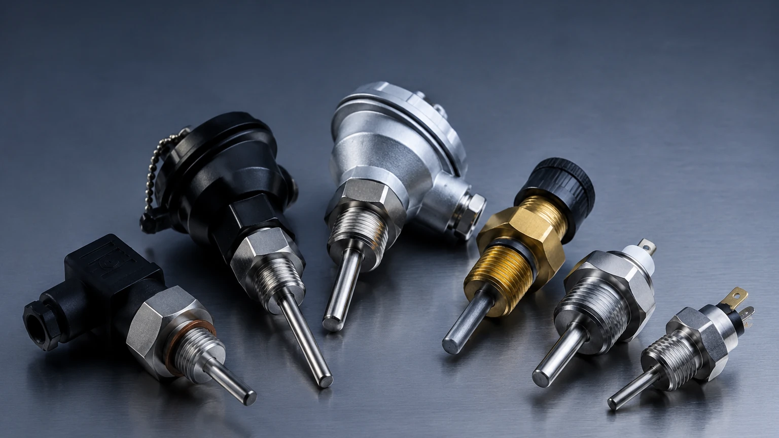
* The Sensing Probe: This contains the thermocouple elements (e.g., Type K, J, or T). It is usually protected by a stainless steel or Inconel sheath. For corrosive environments, specialized coatings or thermowells are used.
* Cold Junction Compensation (CJC): Since the thermocouple measures the difference between the hot and cold junctions, the switch must account for the ambient temperature at the terminal block. Modern electronic switches use an internal thermistor to measure the terminal temperature and mathematically compensate for it.
* The Controller/Switching Unit: This housing contains the electronics for signal amplification, setpoint adjustment, and the output relay. In many industrial setups, this unit is DIN-rail mounted in a control cabinet or integrated into a field-mount explosion-proof housing.
* Output Contacts: Typically provided as SPDT (Single Pole Double Throw) or DPDT (Double Pole Double Throw) relays, allowing for both "normally open" and "normally closed" configurations.
Selection Criteria for Industrial Applications
Selecting the right thermocouple switch requires an analysis of the process environment and the required safety margins. Use the following criteria to evaluate options:
1. Thermocouple Type and Range
Different metal combinations provide different temperature ranges and sensitivities. The most common types used in switching applications include:
| Type | Materials | Temperature Range (°C) | Characteristics |
| :— | :— | :— | :— |
| Type K | Chromel / Alumel | -200°C to +1,260°C | Most common, wide range, good oxidation resistance. |
| Type J | Iron / Constantan | 0°C to +750°C | High sensitivity, limited range, prone to oxidation. |
| Type T | Copper / Constantan | -200°C to +350°C | Excellent for cryogenic and low-temperature applications. |
| Type N | Nicrosil / Nisil | -270°C to +1,300°C | High stability at high temperatures, resists green rot. |
| Type R/S | Platinum / Rhodium | 0°C to +1,450°C | Noble metals, used for extremely high-temperature processes. |
2. Setpoint Accuracy and Hysteresis
Accuracy refers to how close the switch triggers to the actual physical temperature. Hysteresis (or deadband) is the difference between the setpoint where the switch activates and the point where it resets. For example, if a high-temperature alarm is set at 500°C with a 5°C hysteresis, the switch will trigger at 500°C but will not reset until the temperature drops back to 495°C. This prevents the system from rapidly cycling on and off.
3. Response Time
The time it takes for the switch to react depends largely on the mass of the probe and the presence of a thermowell. For applications requiring rapid shutdown (e.g., preventing a chemical runaway reaction), thin-diameter probes or grounded junctions are preferred to minimize thermal lag.
4. Environmental Protection
In industrial automation, the switch housing must match the site conditions. This includes IP65/67 ratings for water and dust ingress or ATEX/IECEx certifications for hazardous areas where explosive gases or dust may be present.
Integration with Level Measurement Systems
In many process industries, temperature and level measurement are inextricably linked. For instance, in high-pressure steam boilers or chemical reactors, a drop in liquid level can lead to a rapid rise in temperature, potentially damaging equipment.
Thermocouple switches are often used as a redundant safety layer alongside instruments like radar level meters or magnetic level gauges. While the level meter monitors the volume, the thermocouple switch acts as a "high-limit" safety cut-off. If the process temperature exceeds safe limits due to a level failure or heating malfunction, the switch can immediately isolate the heat source.
For a comprehensive view of how these technologies integrate into a complete process control strategy, engineers often Review product options and application support to ensure that temperature switches and level sensors are compatible in terms of signal output and enclosure ratings.
Installation and Wiring Guidelines
Proper installation is paramount to ensure the reliability of thermocouple switches. Incorrect wiring is the leading cause of "drift" or false triggering.
1. Use Correct Compensation Cables: You must use extension wires made of the same materials as the thermocouple itself. Using standard copper wire between the probe and the switch will create new, unintended thermocouple junctions at the terminals, leading to massive errors (often 20°C to 50°C or more).
2. Avoid Electromagnetic Interference (EMI): Thermocouple signals are very weak (millivolts). Wiring should be kept away from high-voltage power lines, motors, and frequency inverters. Use shielded cables and ensure the shield is grounded at only one end to avoid ground loops.
3. Probe Immersion Depth: To avoid errors caused by thermal conduction along the probe sheath (stem conduction), the probe should be immersed into the process fluid to a depth of at least 10 times the probe diameter.
4. Thermowell Considerations: If the process involves high pressure or high flow velocities, the thermocouple should be installed in a thermowell. While this protects the sensor, it increases response time. Using a thermal transfer paste inside the thermowell can help mitigate this lag.
Common Risks and Limitations
While thermocouple switches are robust, they are not without limitations:
* Drift and Aging: Over time, the metal wires in a thermocouple can undergo chemical changes or oxidation, especially at high temperatures. This causes the millivolt output to shift, meaning the switch may trigger at the wrong temperature. Periodic calibration is required.
* Cold Junction Errors: If the switch is mounted in an area with rapidly fluctuating ambient temperatures, the internal compensation may struggle to keep up, leading to temporary inaccuracies.
* Sensitivity to Contamination: In non-sheathed thermocouples, exposure to certain gases can "poison" the metals, altering their thermoelectric properties. Always use sheathed or protected probes in reactive environments.
* Lower Accuracy than RTDs: For temperatures below 600°C, Resistance Temperature Detectors (RTDs) generally offer better accuracy and stability. Thermocouples are preferred primarily for their higher temperature limits, faster response, and durability in high-vibration environments.
Frequently Asked Questions (FAQs)
Q: Can I use a single thermocouple for both a continuous display and a switch?
A: It is possible using a signal splitter or a controller that provides both a 4-20mA output and relay contacts. However, for safety-critical applications (SIL-rated systems), it is often recommended to have a dedicated thermocouple switch independent of the primary control loop.
Q: What is the difference between a grounded and an ungrounded thermocouple switch?
A: In a grounded thermocouple, the junction is physically welded to the protective sheath. This provides a very fast response time but makes the system susceptible to electrical noise. An ungrounded thermocouple is electrically isolated from the sheath, providing better noise immunity at the cost of a slower response.
Q: How often should thermocouple switches be calibrated?
A: In most industrial settings, an annual calibration check is standard. However, in high-temperature processes (above 1000°C) or highly corrosive environments, semi-annual or quarterly checks may be necessary to account for sensor aging.
Q: Can thermocouple switches handle high-current loads directly?
A: Most integrated thermocouple switches have relay contacts rated for 2A to 10A at 250VAC. If you need to switch a heavy industrial heater or a large motor, the thermocouple switch should trigger an external heavy-duty contactor.
Conclusion
Thermocouple switches remain a cornerstone of industrial thermal safety. By converting the Seebeck Effect into actionable binary logic, they provide a reliable, cost-effective method for protecting equipment and personnel from temperature excursions. When integrated correctly with other process instruments—such as the level measurement solutions found on the Welk Main Page—they form a robust defense against process failures. Successful implementation relies on selecting the correct thermocouple type, ensuring proper wiring with compensation leads, and adhering to a strict maintenance and calibration schedule.