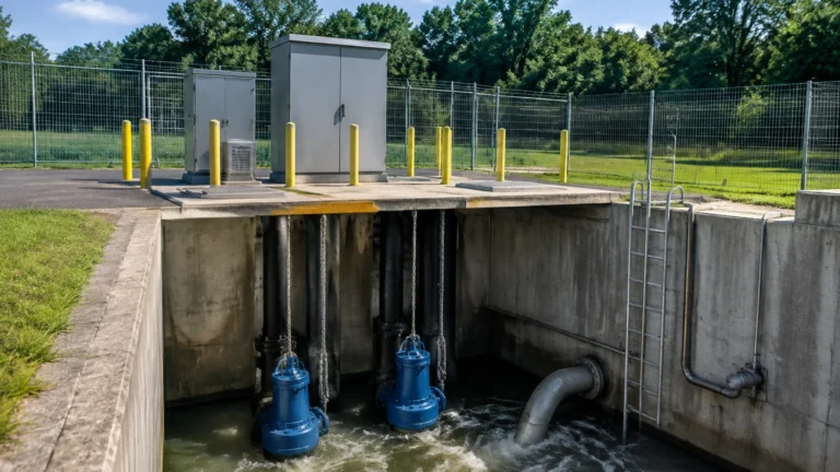
Resistance Thermometer Device
Resistance Thermometer Device
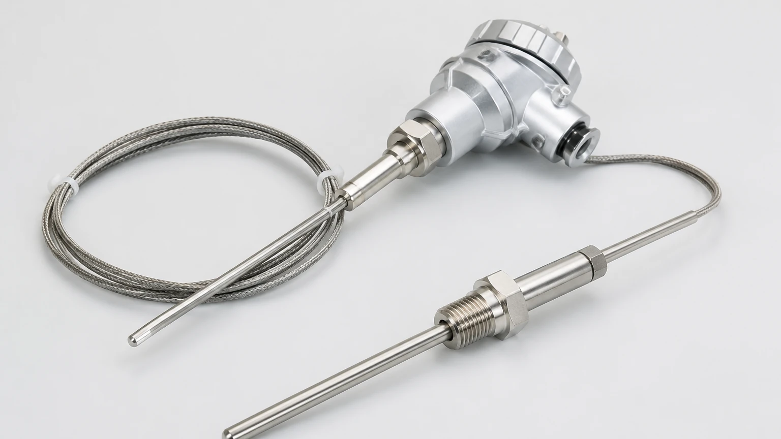
In the landscape of industrial process control, the resistance thermometer device (RTD) stands as one of the most reliable and accurate instruments for temperature measurement. Often referred to simply as a resistance thermometer, this sensor operates on the fundamental physical principle that the electrical resistance of a metal changes in a predictable and repeatable manner with variations in temperature. For engineers and facility managers involved in water treatment, chemical processing, and industrial automation, understanding the nuances of the resistance thermometer device is essential for ensuring process stability and safety.
While level measurement is often the primary focus in tank management, temperature is a critical secondary variable. Changes in temperature affect fluid density, which in turn impacts the accuracy of hydrostatic level transmitters. Furthermore, high-precision radar level meters often require temperature compensation to maintain their specified accuracy. This guide explores the technical foundations, selection criteria, and practical applications of the resistance thermometer device within industrial environments.
Measurement Principles of the Resistance Thermometer Device
The operation of a resistance thermometer device is based on the Positive Temperature Coefficient (PTC) of metallic conductors. As the temperature of the metal increases, the thermal agitation of the atoms within the crystal lattice increases. This increased agitation creates more frequent collisions with moving electrons, thereby increasing the electrical resistance of the material.
The Resistance-Temperature Relationship
For most metals used in RTD construction, the relationship between resistance ($R$) and temperature ($T$) is nearly linear over a specific range. This relationship is mathematically defined by the Callendar-Van Dusen equation for temperatures above 0°C:
$R_t = R_0 [1 + At + Bt^2]$
Where:
* $R_t$ is the resistance at temperature $t$.
* $R_0$ is the resistance at 0°C (typically 100 Ω for a Pt100 sensor).
* $A$ and $B$ are constants derived from the properties of the metal.
Sensing Elements and Materials
Platinum is the most common material used in the construction of a resistance thermometer device due to its chemical inertness, wide temperature range, and excellent linearity. Other materials include:
* Platinum (Pt): The industry standard (e.g., Pt100, Pt1000). It covers a range from -200°C to +850°C.
* Nickel (Ni): Offers higher sensitivity than platinum but has a limited temperature range and is prone to oxidation.
* Copper (Cu): Highly linear but has a low base resistance and is susceptible to oxidation at higher temperatures.
Construction Types: Thin-Film vs. Wire-Wound
When selecting a resistance thermometer device, the physical construction of the sensing element determines its durability and response time. There are two primary types used in industrial automation:
1. Thin-Film RTDs
Thin-film elements are manufactured by depositing a thin layer of platinum onto a ceramic substrate using vacuum evaporation or sputtering. The layer is then etched to create the resistive circuit. These sensors are compact, highly resistant to vibration, and cost-effective. They are the preferred choice for most standard industrial applications.
2. Wire-Wound RTDs
Wire-wound elements consist of a fine platinum wire coiled around a ceramic or glass mandrel. This construction allows the wire to expand and contract freely with temperature changes, minimizing mechanical strain. While more expensive and sensitive to high vibration, wire-wound sensors offer superior accuracy and stability over very wide temperature ranges.
Wiring Configurations and Lead Wire Compensation
A significant challenge in using a resistance thermometer device is the resistance added by the lead wires connecting the sensor to the transmitter or controller. If not compensated for, this lead resistance is added to the sensor's resistance, leading to a "false" high temperature reading.
| Configuration | Description | Accuracy Level | Application |
| :— | :— | :— | :— |
| 2-Wire | Two leads connect the RTD to the circuit. No compensation for lead resistance. | Low | Short distances, low-precision monitoring. |
| 3-Wire | Uses a third wire to measure and subtract lead resistance. The industry standard. | Medium-High | Industrial process control, chemical tanks. |
| 4-Wire | Uses two wires to carry the current and two to measure voltage. Eliminates lead resistance entirely. | Highest | Laboratory calibration, custody transfer. |
In most B2B industrial scenarios, the 3-wire configuration is the most common, providing a balance between cost and accuracy. For high-precision applications, such as those found on the Main Page of advanced instrumentation catalogs, 4-wire systems are recommended to ensure the highest data integrity.
Selection Criteria for Industrial Applications
Choosing the right resistance thermometer device requires a thorough evaluation of the process environment. Engineers must consider the following factors:
1. Accuracy Classes (IEC 60751)
RTDs are categorized into classes based on their tolerance at specific temperatures:
* Class AA (1/3 DIN): $\pm(0.1 + 0.0017 |t|)$ °C
* Class A: $\pm(0.15 + 0.002 |t|)$ °C
* Class B: $\pm(0.3 + 0.005 |t|)$ °C
2. Temperature Range
Ensure the sensor and its sheath material can withstand the process extremes. While the platinum element might handle 800°C, the insulation or epoxy used in the probe assembly might fail at 250°C.
3. Response Time
In dynamic processes, the time constant ($T_{90}$) is critical. Thin-film sensors generally respond faster than wire-wound sensors. The use of a thermowell will significantly increase the response time, which must be accounted for in the control loop logic.
4. Chemical Compatibility
The sheath material (usually Stainless Steel 316L, Inconel, or Hastelloy) must be compatible with the process media. In corrosive chemical applications, specialized coatings like PTFE may be required.
Integration with Level Measurement Systems
In the context of industrial automation, the resistance thermometer device is rarely used in isolation. It is a vital component of integrated level and temperature measurement solutions. For example:
* Hydrostatic Level Transmitters: These sensors measure the pressure exerted by a liquid column. Since liquid density changes with temperature, an RTD provides the data necessary for the transmitter to calculate the true level regardless of thermal expansion.
* Magnetic Level Gauges: High-temperature applications in oil and gas require RTDs strapped to the gauge chamber to provide real-time temperature feedback to the control room, ensuring the float remains within calibrated limits.
* Ultrasonic Level Sensors: The speed of sound in air is highly dependent on temperature. Integrated RTDs allow ultrasonic sensors to adjust their calculations, preventing measurement errors caused by fluctuating air temperatures in the tank headspace.
Installation Considerations and Best Practices
To ensure the longevity and accuracy of a resistance thermometer device, proper installation is paramount. Follow these engineering guidelines:
1. Immersion Depth: To prevent heat conduction errors (where heat travels along the sheath to the outside environment), the sensor should be immersed to a depth at least 10 times the diameter of the protection tube.
2. Thermowell Usage: In high-pressure or high-velocity flows, always use a thermowell. This allows for sensor replacement without breaking the process seal. Ensure the use of thermal transfer paste inside the thermowell to minimize lag.
3. Vibration Mitigation: If the installation point is subject to heavy vibration (e.g., near a pump), use thin-film RTDs and ensure the probe is securely supported. Excessive vibration can cause mechanical fatigue in wire-wound elements.
4. Shielding and Grounding: Use shielded twisted-pair cables for signal transmission to protect against electromagnetic interference (EMI), which can distort the small resistance changes measured by the controller.
Limitations of the Resistance Thermometer Device
While highly accurate, the RTD is not suitable for every application. Limitations include:
* Self-Heating: The current passed through the RTD to measure resistance generates a small amount of heat. If the current is too high, it can cause a measurement error. Industrial transmitters typically limit this current to less than 1 mA.
* Cost: RTDs are generally more expensive than thermocouples, particularly for high-temperature ranges where platinum usage increases.
* Fragility: Despite modern construction, the ceramic components in RTDs can be susceptible to thermal shock or extreme mechanical impact compared to the rugged junction of a thermocouple.
Frequently Asked Questions (FAQs)
Q: What is the difference between Pt100 and Pt1000?
A: A Pt100 sensor has a resistance of 100 Ω at 0°C, while a Pt1000 has 1000 Ω at 0°C. Pt1000 sensors are better for battery-powered applications because they require less current, and they are less sensitive to lead wire resistance in 2-wire setups.
Q: How often should a resistance thermometer device be calibrated?
A: In standard industrial applications, annual calibration is recommended. However, in high-vibration or high-temperature environments where sensor drift is more likely, semi-annual checks may be necessary.
Q: Can I use an RTD in a vacuum?
A: Yes, but heat transfer is slower in a vacuum. You must ensure the sensor has a good mechanical connection to the surface being measured or use a design specifically rated for vacuum service to prevent overheating from the sensing current.
Conclusion
The resistance thermometer device remains a cornerstone of precision temperature measurement in the B2B sector. Its stability, linearity, and accuracy make it indispensable for complex processes where even a minor temperature fluctuation can lead to significant product loss or safety risks. By carefully selecting the appropriate wiring configuration, element type, and installation method, engineers can ensure reliable data for their automation systems. For those seeking comprehensive measurement solutions, exploring the technical resources and product options available on the Main Page of professional instrumentation providers is the recommended next step in optimizing process performance.