Rtd Accuracy
Rtd Accuracy
In the landscape of industrial process control, precision is not merely a preference but a requirement for safety, efficiency, and product quality. Resistance Temperature Detectors (RTDs) are widely regarded as the gold standard for temperature measurement in B2B environments ranging from chemical processing to water treatment. Understanding rtd accuracy is essential for engineers and procurement specialists who must balance high-performance requirements with cost-effective instrumentation strategies.
This guide provides a technical deep dive into the factors defining RTD precision, the international standards governing their performance, and practical considerations for maintaining accuracy in demanding industrial applications. As a professional manufacturer of measurement instruments, Welk emphasizes that temperature data often serves as a critical secondary variable in level measurement and automation systems.
The Fundamental Principles of RTD Temperature Measurement
Before evaluating accuracy classes, it is necessary to understand how an RTD functions. The operation of an RTD is based on the predictable change in electrical resistance of a metal in response to temperature fluctuations. Most industrial RTDs utilize platinum (Pt) due to its chemically inert nature, wide temperature range, and highly linear resistance-to-temperature relationship.
The Temperature Coefficient of Resistance (Alpha)
When the temperature of the metal increases, the thermal agitation of the atoms increases, which in turn increases the resistance to electron flow. For a standard platinum RTD, this relationship is defined by the "Alpha" (α) coefficient, which represents the average change in resistance per ohm per degree Celsius over the range of 0°C to 100°C. The most common standard is the DIN/IEC 60751 coefficient of 0.00385 Ω/Ω/°C.
Resistance at Ice Point
RTDs are typically categorized by their resistance at 0°C. The Pt100 (100 ohms at 0°C) is the industry standard, though Pt1000 (1000 ohms at 0°C) sensors are increasingly used in applications where lead wire resistance might otherwise compromise accuracy. Higher base resistance reduces the relative impact of lead wire errors, which is a critical factor in overall rtd accuracy.
Defining RTD Accuracy Classes and Standards
The accuracy of an RTD is not a single fixed value but a range defined by international standards, most notably IEC 60751. This standard categorizes sensors into accuracy classes based on their tolerance at specific temperatures.
Tolerance Calculations
The tolerance (Δt) for an RTD is generally expressed by the formula:
Δt = ±(a + b|t|)
Where 'a' is the fixed error at 0°C, 'b' is the error coefficient per degree, and '|t|' is the absolute value of the temperature in Celsius.
Standard Accuracy Classes
| Class | Tolerance at 0°C (±°C) | Tolerance Formula (±°C) | Typical Application |
| :— | :— | :— | :— |
| Class AA (1/3 DIN) | 0.10 | 0.10 + 0.0017|t| | Laboratory and high-precision chemical processes |
| Class A | 0.15 | 0.15 + 0.002|t| | Critical industrial automation and custody transfer |
| Class B | 0.30 | 0.30 + 0.005|t| | General industrial monitoring and HVAC |
| Class C | 0.60 | 0.60 + 0.01|t| | Non-critical auxiliary systems |
It is important to note that as the temperature deviates from 0°C, the allowable error increases. For instance, a Class A sensor has a tolerance of ±0.15°C at 0°C, but this expands to ±0.35°C at 100°C. For organizations seeking comprehensive instrumentation solutions, reviewing the Main Page of a specialized manufacturer can provide insights into how these sensors are integrated into larger industrial frameworks.
Impact of Wiring Configurations on RTD Accuracy
One of the most frequent sources of error in temperature measurement is the resistance of the lead wires connecting the sensor to the transmitter or controller. Depending on the distance and the gauge of the wire, this can significantly degrade rtd accuracy.
2-Wire Configurations
In a 2-wire setup, the resistance of the lead wires is added directly to the sensor resistance. Because the controller cannot distinguish between the sensor's resistance and the wire's resistance, this leads to a positive temperature offset. 2-wire RTDs are generally only acceptable when using high-resistance sensors (like Pt1000) over very short distances.
3-Wire Configurations
This is the most common industrial configuration. It uses a third wire to measure the lead resistance and subtract it from the total. This assumes that all three wires have identical resistance and are subjected to the same ambient conditions. While effective for most applications, slight imbalances in wire resistance can still introduce errors.
4-Wire Configurations
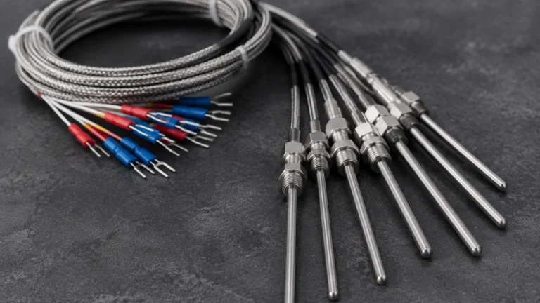
For the highest possible rtd accuracy, a 4-wire configuration is used. This method uses two wires to carry the excitation current and two independent wires to measure the voltage drop across the sensor. Since the voltage measurement circuit has very high impedance, virtually no current flows through the sense wires, effectively eliminating lead wire resistance from the calculation. This is the preferred method for Class AA sensors and laboratory-grade measurements.
Practical Selection Criteria for Industrial RTDs
Choosing the right RTD requires a balance between the required precision and the environmental stressors of the application. When selecting a sensor, consider the following technical factors:
1. Temperature Range: While RTDs are stable, their accuracy is best maintained between -200°C and 600°C. Beyond these limits, sensor drift and material degradation become significant concerns.
2. Vibration Resistance: Thin-film RTDs are generally more resistant to vibration than wire-wound elements. In oil and gas or heavy industrial automation, vibration can cause mechanical fatigue, leading to intermittent signals or total failure.
3. Chemical Compatibility: The sheath material (typically 316 Stainless Steel or Inconel) must be compatible with the process media. In chemical processing, corrosive environments can thin the sheath, eventually affecting the thermal transfer and accuracy.
4. Response Time: The physical size of the sensor and the use of thermowells affect how quickly the RTD reacts to temperature changes. While not a direct component of static accuracy, lag in response can lead to dynamic errors in fast-moving processes.

Installation Best Practices to Preserve Measurement Integrity
Even the highest-quality Class AA RTD will provide inaccurate data if installed incorrectly. To maintain rtd accuracy, engineers should adhere to strict installation protocols.
Immersion Depth
A common error is insufficient immersion depth, which leads to "stem conduction" error. This occurs when heat is conducted away from the sensor through the sheath and into the ambient environment. As a general rule, an RTD should be immersed to a minimum depth of 10 times the diameter of the protection tube (e.g., a 6mm probe should be immersed at least 60mm into the media).
Self-Heating Errors
To measure resistance, a small current must be passed through the RTD. This current generates a small amount of heat ($P = I^2 R$). If the excitation current is too high, the sensor will report a temperature slightly higher than the actual media temperature. Most modern transmitters limit this current to less than 1 mA to minimize self-heating, but it remains a factor in stagnant air or low-conductivity fluids.
Insulation and Shielding
In environments with high electromagnetic interference (EMI), such as near large motors or variable frequency drives (VFDs), shielded cabling is mandatory. Noise coupled into the RTD signal can manifest as fluctuations in temperature readings, effectively destroying the precision of the instrument.
Limitations and Troubleshooting RTD Accuracy Issues
While RTDs offer superior stability compared to thermocouples, they are not without limitations. Understanding these pitfalls is key to effective troubleshooting.
* Drift: Over time, the physical properties of the platinum and the internal insulation can change, leading to a gradual shift in the resistance-temperature curve. Regular calibration is the only way to mitigate this.
* Moisture Ingress: If the seal of the RTD probe is compromised, moisture can enter the sheath. This creates a parallel resistance path (shunting), which typically causes the sensor to read a lower temperature than actual.
* Mechanical Stress: Bending or crushing the probe can strain the platinum element, changing its resistance and permanently altering its accuracy profile.
In many industrial setups, temperature sensors are paired with level measurement devices. For example, in hydrostatic level measurement, the density of the liquid changes with temperature. If the rtd accuracy is poor, the calculated level will also be incorrect. For more information on integrated measurement solutions, professionals often consult the Main Page of specialized manufacturers to ensure all components of their automation loop are compatible.
Frequently Asked Questions (FAQs)
Q: How often should an RTD be calibrated to ensure accuracy?
A: For most industrial applications, an annual calibration is standard. However, in high-vibration or extreme temperature environments, semi-annual checks may be required to detect drift early.
Q: Can I replace a Class B RTD with a Class A without changing my controller?
A: Yes, provided the sensor type (e.g., Pt100) and the wiring configuration are the same. The controller will simply receive a more accurate resistance signal.
Q: What is the difference between Pt100 and Pt1000 in terms of accuracy?
A: Inherently, they follow the same accuracy classes (Class A, B, etc.). However, Pt1000 sensors are more accurate in 2-wire configurations because the lead wire resistance represents a much smaller percentage of the total resistance compared to a Pt100.
Q: Does the thermowell affect RTD accuracy?
A: A thermowell does not change the sensor's inherent accuracy class, but it does introduce thermal lag and potential stem conduction errors. Proper fitment (using thermal paste) and adequate immersion depth are required to minimize these effects.
Conclusion
Achieving high rtd accuracy is a multifaceted challenge that involves selecting the correct tolerance class, utilizing appropriate wiring configurations, and following rigorous installation standards. By understanding the relationship between resistance and temperature, and the international standards that govern it, B2B professionals can ensure their processes remain within optimal thermal boundaries. For those managing complex industrial sites, integrating high-precision temperature sensing with reliable level and flow instrumentation is the cornerstone of modern process automation. To explore the full range of industrial measurement technologies, visit the Main Page for detailed product specifications and application support.